Author: Tim

  • Vert Stab Bottom Nose Rib Problems

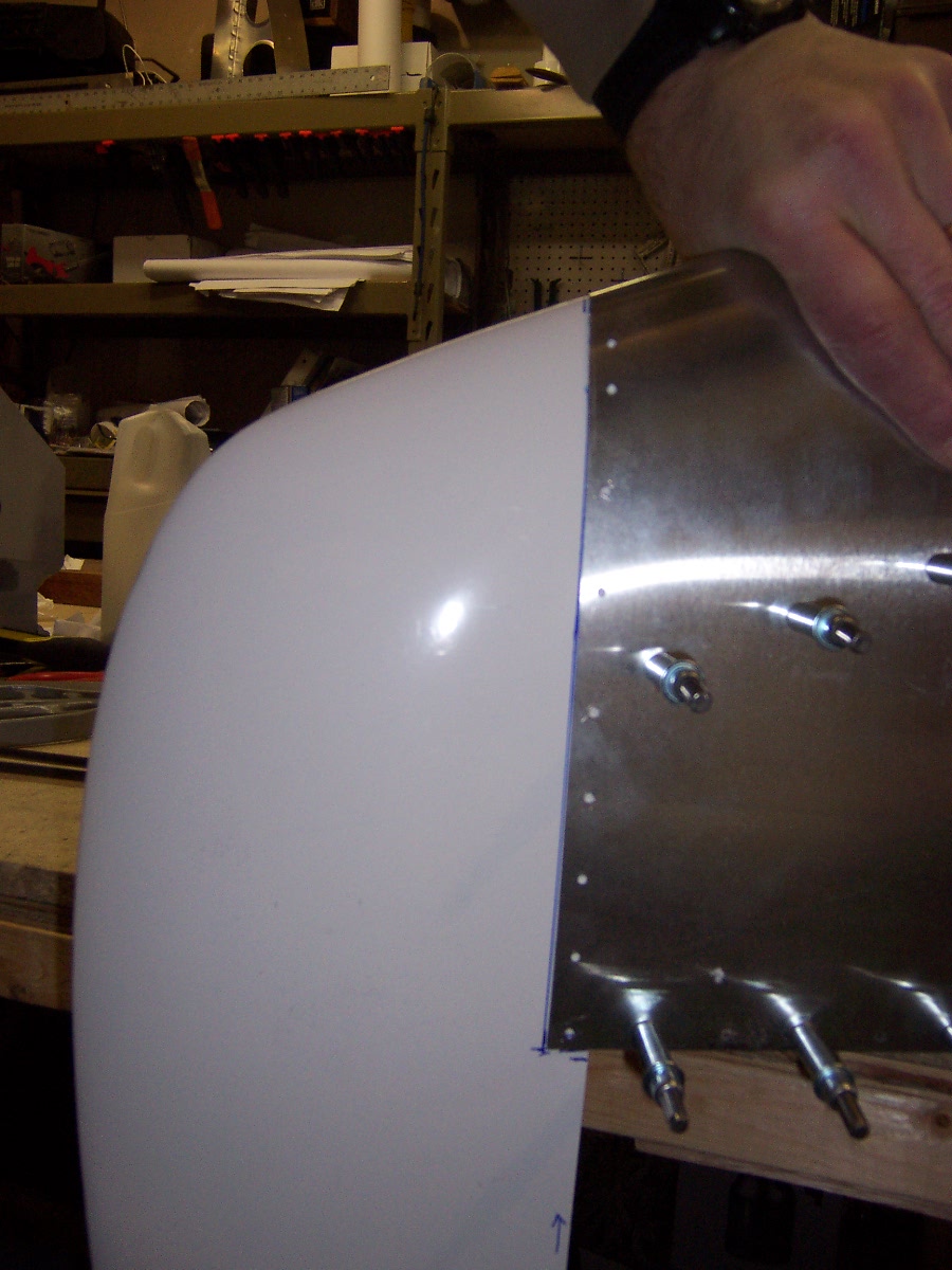
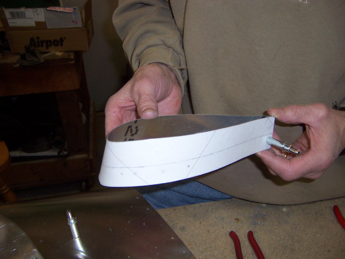
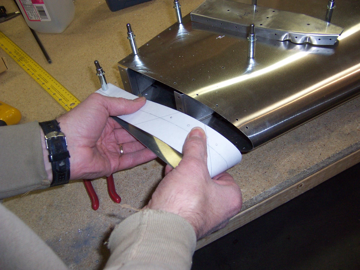
    June 12, 2011  Dan and I have been struggling with the bottom nose rib on the vertical stabilizer.  Dan  fabricated a form block that matched the plans exactly.  When we installed this rib the skin would not sit right, it had a flat or shallow dish.  When I went to rivet it the stems of the pull rivet would break off meaning the ball had pulled up too much.  We are using flush rivets so the rivet holes were dimpled.  We had to Dremel tool the stainless stem off and drill out the poorly set rivet, a real pain.  I think part of the problem is that the natural curvature of the skin does into sit right on the rib, the rib pulls the skin in.  Here is a picture of the rib from the plans sitting in the frame with the skin:

    Vert Stab Plans Rib with Gap

    Notice the gap between the rib and the skin towards the top.

    Dan made some CAD layouts on Autocad increasing the radius at the front of the rib.  Dan made a new form block and made the rib.  Here is a side by side layout.  The primed one on the right is the original design from the plans.  The left one is the new rib

    Very Stab Bottom Ribs

    Here is the new rib sitting in the frame with the skin.  Notice the closer fit.

     Vert Stab Bottom Rib Modified Rib Fit

    Fast Forward to Oshkosh 2011.  I walked the flight line looking at all the completed Sonex planes and noticed that almost all of them had the awkward skin layout at the top of the bottom rib.
    Return To Empennage – Vertical Stabilizer

  • Horizontal Stab Tips

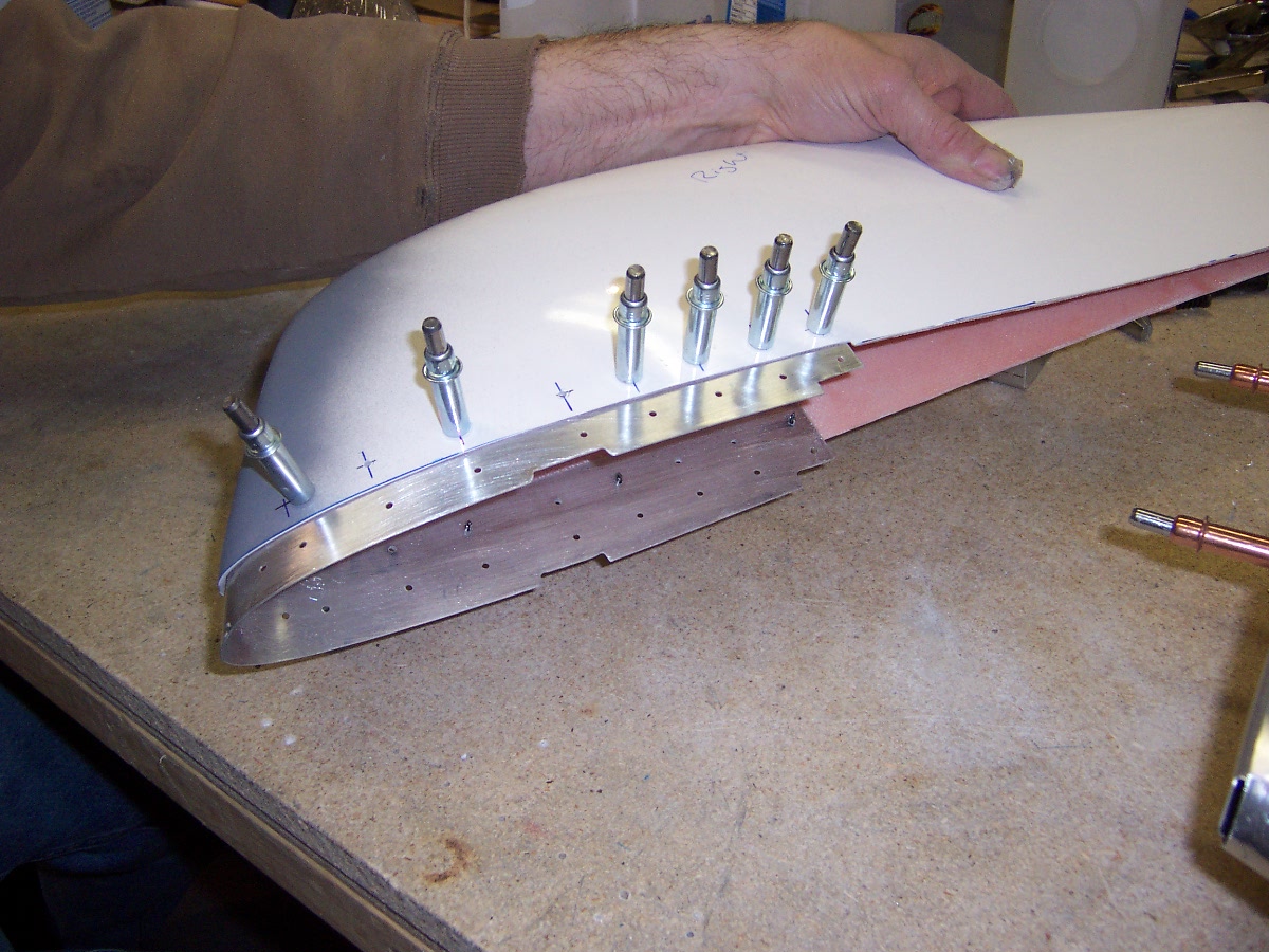
    Dan used the same method from the vertical stab tip for the horizontal tips.  However we decided to rivet the tips since we don’t think we will need to pull them off.  So Dan created  a strip of sheetmetal that mounts between the skin and the frame and extends out under the tip.

    Horiz Stab Tip Splice Strip


    Tip Slice Strip - Notice How Strip Matches the Leading Edge


    Fitting Tip For Trimming


    Measurements For Trim


    Trimming With Dremel

    Still toook a lot of fitting and sanding

    Splice Strip In Tip


    Test Fit Tip

    Notice we have a butt joint of the tip and the skin.  The plans have the tip slip between the skin and the outboard rib.

    Return To Empennage – Horizontal Stabilizer

  • Hoizontal Stab Skins

    The date on thsi if between March and May 2011.  We had created a CAD model of the horizonatal stab skin.  The plotter has 36″ wide roll of paper and the part is begger than that.  So we had to split the drawing and put alignment marks on them to mate them.  If you read the Vertical Stab skin drawing entry, you know we were having trouble with the plotter accuracy over a few feet, and also the paper changes dimensions with humidity.  We tried out best with the alignment and then wrapped the paper around the frame. With a light we could see where the skin holes were with respect to the center of the ribs.  Some were excellent but towards the outboard side it was off a little.

    Horizonyal Stab Skin Drawing Wrapped on Frame

    We used spray adhesive (3M 77, let it flash off a while before mating) to adhere the drawing to the sheet metal and snipped it out and filed it to the line.  Dan measured and used the yard stick jole template to put the row of holes on each side.  We then clecoed the tedges together (using those two rows) and to the table.  We bent the leading edge using a piece of wood along the length.

    We then clamped one edge of the skin to the frame (took a while to get it right on) and match drilled the frame from the skin.  Now the top side we had to match drill the hinge too, so we had 3 pieces we were trying to align perfectly: the skin, the frame, and the hinge.  (On a side note we anted to make sure the two seperate hinge pieces were aligned to each other, hmmmm.)  Now we could cleco an edge of the skin to the frame and use a pen to mark on the inside of the skin where the ribs are located.  In some of the following pictures you might be able to see these lines.  Now we could make sure the skin holes would be in the center of the ribs.  He did this for the top and the bottom of both skins.  Here is Dan drilling out the marked holes

    Drilling Horiz Stab Skin Holes

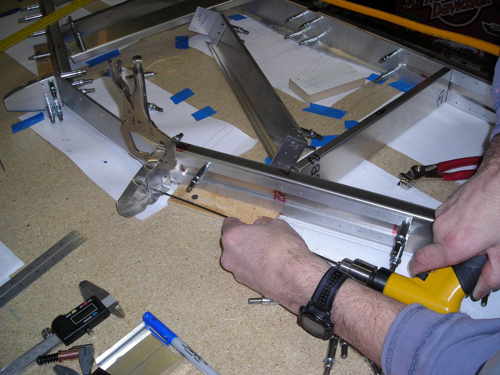
    Match Drilling Frame From Skin
    Horizontal Stab Skins Clecoed On Frame

    Return To Empennage – Horizontal Stabilizer

  • Riveted Vert Stab

    Not sure of the exact date March – April 2011.

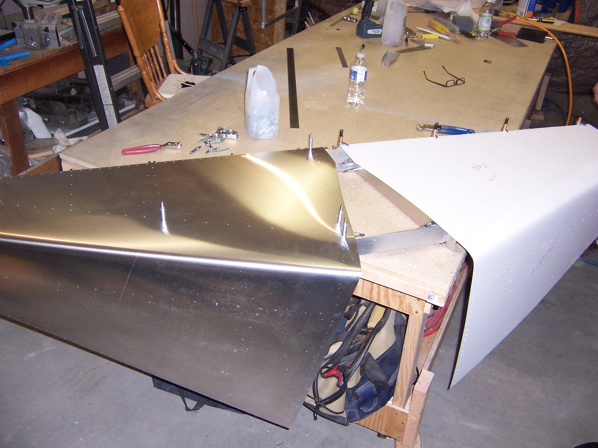
    We riveted the structure together and the skin on on seperate days.  Also riveted the Rudder.  Here is the assumbly test fit together.

    Skins on fest fit

    The fiberglass tip was not straight from the factory at the trailing edge.  Dan used a heat gun to heat up the tup to bring it in.

    Alignment of vertical tip and rudder

    Return To Empennage – Vertical Stabilizer

  • Fabrication of a Vert Stab Nose Rib

    Software messed up some pictures, trying to fix it
    Not sure of the actual date, between Feb – May 2011

    We decided to remake a nose rib for the vertical stabilizer.  Here is what we have learned

    Former and sheet materialLocate FormerDrill holes for clamp screws

    A

    Locate Former

    B

    Drill holes for clamp screws

    C

    Clamp material

    D

    Trace outline with washer with right Inner Radius for rib flange

    E

    Outline with former

    F

    Outline on material

    G

    Drilling Corner radius of flange, makes it easier to snip out

    H

    Blurry pic of outline with corner holes

    I

    Cutting rib out with shears, cutting to the corner holes

    J


    Front and Back cut out


    K

    Cutting Edges, notice plenty of extra to file later

    L

    Mount in form block

    M

    Marking where the flutes are located

    N

    Used fluting pliers at the marks, this helps with the initial forming

    O

    Forming a flange with a mallet, glancing taps/hits to push the metal over

    P

    Forming the flange

    Q

    Using a rod (and hammer) to get the flutes formed

    R

    Formed rib

    Need to trim the front off and clean it up.  Basic forming time is five mintes or less.  Of course it took us a few ribs to figure the process out.

  • New Vert Stab Tip Attachment

    Not really sure of the specific date of this work, let’s just say it was between Feb and May 2011.  Dan I and wanted to have access to the vert stab tip in case we wanted to put a position light or an antenna later on.  Dan found some light weight plastic electrical conduit that he heated up to put a bend in to go from the bottom rib to the top rib.

    Conduit for Vert Stab

    Worsk great, now hoe to make the tip removable.  One method uses an upside down rib attached to the top rib so you have a flange to put nut plates on.  Dan thought of a different solution of making a sheetmetal strip that goes between the skin and the top rib and it projects up to allow a flange for the tip to attach.  I’ll try and find a better picture:

    New Vert Stab Attach Strip in Place With Top Rib

    The vert stab top rib is on the bottom, the new strip is on the outside and the stip extends up under the fiberglass tip.  A great feature of this solution is that it supports the nose of the tip all the way around.  Here is the back end of the tip

    Here is Dan holding the complete assembly.

    New Vert Tip Attach Method
    New Vert Tip Attach Method Assembled

    So the fiberglass tip will butt up against the skin instead of going under it.  Dan did a fantastic job of mating these to edges.

    Vert Stab Tip Skin Joint (Wicked Nice)

    Where the silver clecos are above we will have nutplates behind the stip so washer head screws will secure the tip on.

    Here is the horizontal alignment and end alignment with the rudder

    Vert Stab Tip & Rudder Alignment (Sweet)

    Return To Empennage – Vertical Stabilizer

  • Completed Horizontal Stabilzer Frame

    Saturday Jan 8, 2011  (5 hours)

    We finished locating and match drilling the spars

    Locating the last spar

    We had not attached the T06-06 Clip to the T06-03 Forward Spar Fitting.  To locate those horizontally the plans show a dimension from the center of a mounting hole on the Forward Spar Fitting, a tricky measurement to make.  We used a centerline mark on the Forward Spar Fitting out to the rib .  Vertically we used a centerline and checked with the Leading Edge Rib.

    Took me a little while to catch up to how Dan was locating the Leading Edge Ribs (T04-06) to the Forward Spar Assembly (T03-05).  We cut a .125 thick piece of aluminum as the spacer to locate the rib away from the spar.  Dan had previously marked the vertical centerline of the rib and the centerline of the spar.  To align these marks we used a shim between the bottom of the rib and the table (turns out the thickness os a ruler and a piece of .032 was perfect).  With the rib aligned we matched drilled it in place.

    Checking Position of Rib
    Match Drilling Ribs, 12″ drill bit since rib so close to the table
    Ribs in place

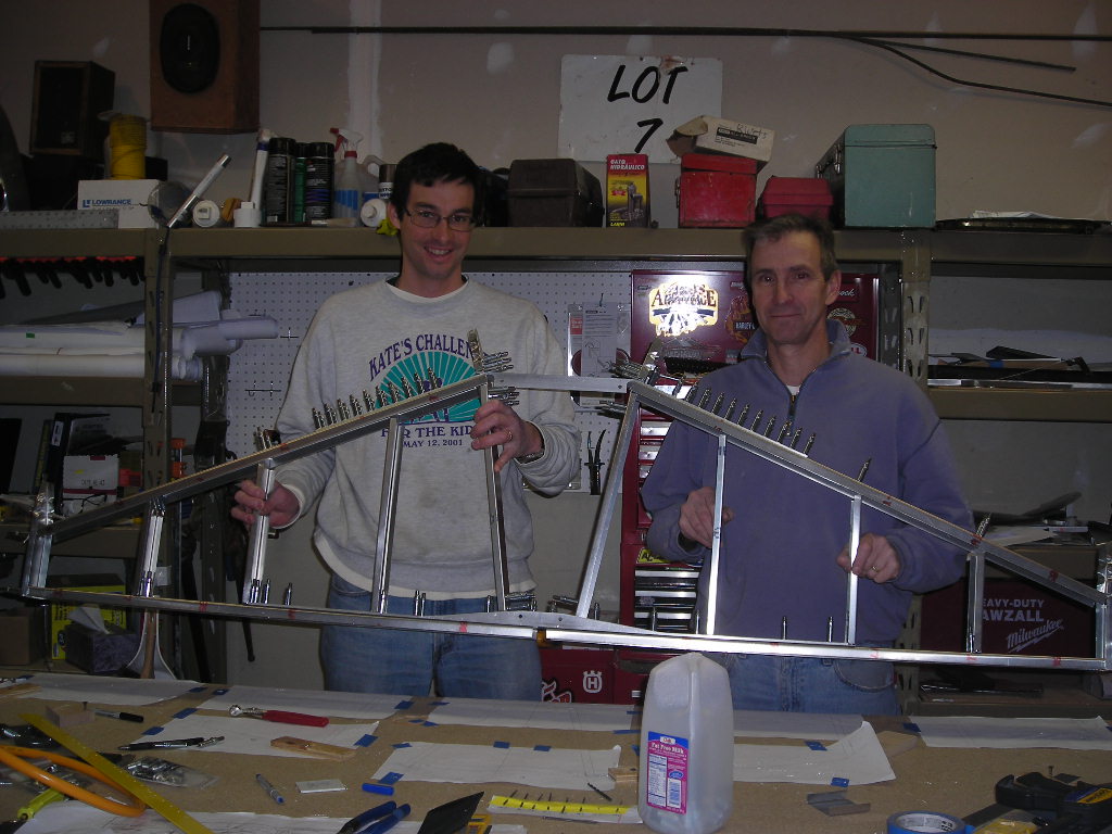
    Dan used his paper templates to locate the tip ribs on the frame.  The frame is complete!

    Frame Complete!
    Nice and Straight!

    Once we had the frame match drilled and cleco-ed together we decided to up drill to a #30 right away (just the frame assembly holes, not the skin holes).  Sure was nice having one person pull clecos while the other kept drilling.  We used a 6″ #30 drill bit in a couple spots, like on the tip ribs which were close to the bench top.

    We cut a section of .025 for the rudder skin off a 4’x8′ sheet.  The cut was full width (4′) and we scored it.  We line up the score cut with the end of the table, place a 4′ straight edge underneath, clamp it down and push down on the other side of the score with a piece of 4′ steel angle.  The two us were pushing pretty hard to get the sheet to break (we even flexed the scoring by rotating the sheet up and down).  We need to find a better method, especially  when we need a piece of .032,  so we might try a router next.  A variable speed at its slowest rpm might be the trick.

    Return To Empennage – Horizontal Stabilizer

  • Hinge Template & Rudder Skin Trim

    Bought sacrificial ruler to drill hinges.  Studied hinges for rudder to make sure cuts lengths and locations were understood.  Trimmed sample rudder to size and marked final rudder skin.

    Return To Rudder

  • Rudder Ribs

    The rudder ribs are bent from .025″ sheet metal.  (more…)

  • Paper Skin On Vertical Stab Frame

    Dan cut out a CAD print of the skin on the vertcal stab

    The rivet locations lined up very well with the spars.  The paper skin helped align the shape on the frame.

    Return To Vertical Stabilizer – Empennage Page

Back