Dan
Dec. 8, 2013 Last day for major work on right wing
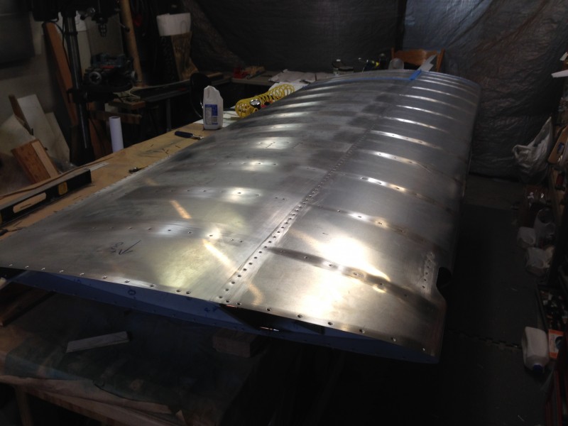
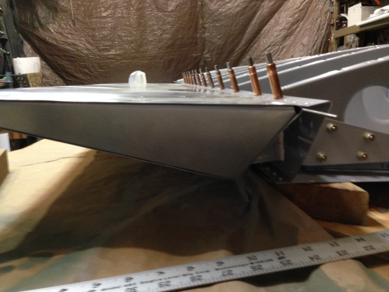
There were plenty of interruptions yesterday and today but the right wing is finally closed in and riveted with not much but a few small items to do before wing installation on the fuselage.
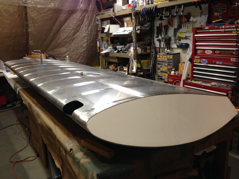
Right Wing – Tip SideTie Down Ring & Inspection PlateRight Wing Tip Installed (Wing Upside down)Right Wing Tip Installed (Wing Upside down, Note Landing Light Pocket)Right Wing – Note Pitot, Static, & AOA tubesRight Wing – Inside view of wing tip through the landing light cut out (wing is upside down)
Left To Do:
Paint control rods
Add nut plates for surface screws on wing tip
Trim pitot, static and AOA tubes and connect to lines.
Attach and trim wing doubler skin after wing is fitted to fuselage
A few things to note.
The rivets in the bags need to be watched carefully because they are not perfectly sorted. Either we inadvertently dropped a few CCP rivets in the CCC bag or they came that way. in either case, I caught them before pulling the rivets but it is a lesson to not be too casual or in too much of a hurry when putting in large numbers of rivets like those in the wing assembly.
Using the flat piece of 3/16″ aluminum between the rivet gun and the rivets was a big improvement over just using the rivet gun tip. This was particularly true when riveting the leading edge skin to push with heavy and even pressure to keep the skin tight to the ribs. It probably helped a lot to have the skin well formed with the vacuum method but even so, I think it helps to be able to press hard on when riveting the leading edge.
I was planning on hanging the wings up on the wall in the garage but I think I can rearrange the material in the rolling rack and put the wings on the rack.
Modifying the rack with have to be the next thing to do so I can clear off the bench to assemble the left wing.
Dan Dec. 6, 2013 – Right wing internal checks before final rivet closure.
So last night I expected tonight would be a lost night due to other commitments. As it turns out, everything opened up and my evening was open. Being below zero F there are few that want to go out so I turned on the heat in my garage and went to work. During the day Tim and I had talked over the alternatives. Rivet the skins as they are without opening it up to tighten down the tie down eye bolt (I had neglected to do this before closing it all up but it was possible to get at it from the inspection hole. On my way home I decided to try and get to the tie down bolt through the access hole by hanging the wing over the edge of the bench. I figured that if it seemed reasonable to torque the bolt down from there I would just either torque it then and there of else if it appeared too awkward I would pull the clecos off the top aft skin and torque the bolt. I messed with the bolt for about a half hour and thought I would try to tighten it from the inspection cover but while I think it was possible, I though it would be much easier (and in the end faster) to pull the top aft skin off. It only took a few minutes to do and once I was ready to begin torquing the nut, I realized that while I had 3 torque wrenches in my shop, only one was well suited for the 200 or so inch lbs for the 3/8 x 24 bolt. Problem was that the 9/16 hex socket required a 3/8″ drive. The only torque wrench I had that would work with any reliability at this setting was (Tim’s) 1/4″ drive torque wrench. I have no 1/4″ drive sockets that go above 1/2″. So, off to the store (Fleet Farm) I went to either get a socket at 9/16″ with 1/4″ drive, an adapter for a 1/4″ socket drive to a 3/8″ ratchet or a new torque wrench. I was not in the mood to go running around town at 8:30 on a cold as heck Friday night looking for wrenches and when the only option available at Fleet Farm was a new torque wrench, I bought it. Back at home it took little time to torque the nut on the eye bolt.
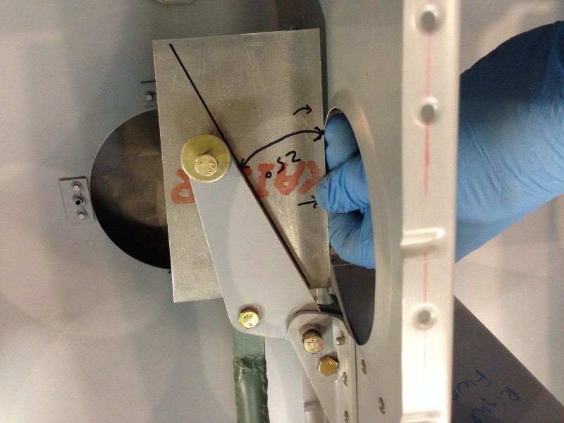
After the bolt I started looking at the bell crank and the control rods and thought about the rigging for the aileron. It would be possible to do when everything was closed but I could do it much faster with everything open as it was. So, I set up the bell crank by adjusting the short control rod to the aileron length as shown in the drawings at 25 degrees with the aileron at a neutral position.
Setting Aileron Bell Crank
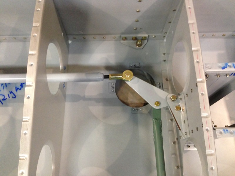
With this done I decided to connect the long control rod and make sure there were no surprises with interference over the expected motion of the aileron.
Aileron Control Rods
As far as I could tell, this all looked good and the pictures show the aileron at full deflection points,
either when the bell crank is at its end of travel of the aileron counter weight stops the aileron from further deflection.
Once again, I ready for final assembly of the wing and this time I think its real. Tomorrow i will close the wing up and then will have to deal with where will put the wing. I am thinking of building a rack on one of the few remaining open walls. We will see how it goes.
Dan cut out the top and bottom skins. Now it was time for the dreaded forward skin with the leading edge bend. The factory suggested a U shaped wooden channel and a guillitine type press that pivots on one end. Think of a paper cutter at the office. This seems kinda drastic but it must work. We had looked on the internet about the different ways people do this. Some have used the same wodden U channel but the center piece is actuated down level by two threaded rod jack screws. Finally there is the vacuum method that uses a pipe at the inside of the leading edge and you wrap the sink in some polymer sheeting and suck the air out with a shop vac. The pressure drop on the large sides of the skin pulls the metal in. There are several YouTube videos on this and we liked the result. So we tried it. The following pictures on the second side. We already had the experience of the first.
First we need to mark the sheet. Sonex provides a set of X-Y points for both ends since these are interesting curves as they wrap around the leadign edge. I used CAD to make a spline fo the curves and plotted it out. We aligned the plot with the bearest row of rib rivets and traced the line. We movd the plot over so we have an offset to cut on. We can file down to the line later.
Traced Skin Edge
Now marking and double checking the center line of the skin
Marked end with offset:
Cutting out the skin with the electric shears (they are great)
There is some technique to the electric shearsyou have to tilt is at the right angle and feed at the right rate, Dan has the golden touch (I think he pratices every morning before breakfast):
Now we lay the skin on top of the poly sheeting:
Since the pipe will lay directly on the centerline we made a mark on either side of the center line of radius of the pipe. We used 1.5 inch diameter black (gas) pipe schedule (? thick). We double checked these marks and used a square on the edge of the pipe to line up with the mark:
Dan had tried pipe flange clamp but didn’t like the results so we used muffler clamps. They seemed really stiff.
Double checking the pipe location by a measurement from the pipe to the outer edge:
Next step is to bring the two long edges together. This is accomplish slowly using tape by working your way down one side and back again, down and back… Takes a while but you need to be gentle so the skin doesn’t bend. Two people makes it go quicker.
Got the top edges touching:
As you do this you are moving from tape piece to piece. With hindsight you really want to make sure the two sides are lined up precisely at the top. Now we folded the poly over and tucked it under, folded the other side over, twisted the ends and tied with wire:
We put the shop vac hose in one end:
We used a smaller shop vac but it worked just fine. (I wanted to borrow a 3/4 hp industrial blower from work but Dan veto-ed that.)
After taking a deep breath we pulsed the shop vac on and sure enough the poly collapsed and made a beautiful teardrop shape of the skin. We let the vac run for a little but all the bending was done. All that prep work for 26 seconds of vacuum forming, (I have a movie of it but need to upgrade this blog to show it). Here is our unwrapped result (still taped at the top)
Now you have to un-tape it slowly maybe .5 inch a time at each tape strip and work back and forth:
Finally you have a leading edge skin, we are really happy with the process, the relaxed bend is close to the assembled leading edge Dan made in the Sonex workshop. We didn’t get any wrinkles or kinks which was a huge relief.
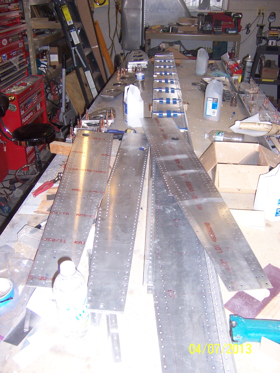
The wings structures are all together and ribs up drilled to the front and rear spars.
Next step is the wing skins. We thought we had been pretty clever in our 4′ x 12′ aluminum sheet planning but we discovered once we laid out the wing skins on what is left we will need to buy another sheet for a fuselage skin. With hindsight we should have cut out the wing and fuselage skins and put them aside. No biggie.
Dan had cut out the top and bottom skins. Note that the aluminum sheets are not perfectly square from the mill. A good framing square will show it.
Dan and I were looking over the rivets and Dan spotted a couple that were just OK. One in particular had a little angle on it, so after a short discussion we decided to give it a couple hits from the rivet gun and bucking bar to flatten it out. As you are probably thinking, we should have left it alone. The bucking bar tilted in my hands and the shop head looked horrible, we were so annoyed. One more to drill out. This row is the -12 lengths which is the longest and you really don’t want to enlarge the hole. Dan drilled it out really well, I’ll have to call him the surgeon. Here is a couple pictures of the new rivet before and after. Notice we put tape on the angles around the bucking bar to prevent scratches.
Dan put the spar halves together with clecos and the five assembly holes mated really well. (We use wing nut clecos here because you can really draw them up tight.)
Dan & I worked on the inboard rivets. In this area the spar caps are the widest so one needs to pay more attention to the rivet gun and bucking bar. This is also where the flush rivets are. In addition there are angles on the spar web that make it thicker. This means longer rivets and for some reason they are harder to set perfectly, especially the long flush ones. Here is our progress for the day:
Dan is really good using the rivet gun with the flush set. But I had “issues” with the bucking bar on these rivets in the top row of the picture. (by the way the spar is mounted upside down).
The plans call out for -12 lengths but our rivet gauge shows they were a tad too long. We had trouble on the Right Spar in this spot but we thought we had more experience now so we tried it. The first was OK but the second and third collapsed to one side, its like they form the head offset from the main stem. These were a pain to drill out due to their length. We decided to heed the rivet gauge and sand down the rivets a 1/16 or so so they fit the gauge. I still had trouble and a few collapsed off-center. What a pain. Dan was not having fun drilling these out. It was a long frustrating session. I was probably tilting the bucking bar as it collapsed but the process happens so fast I am not sure what happens. In the photo below you can see a row of holes that you need a special bucking bar to access due to distance between the angle and the spar cap (see this post):
Our tool from the Right Hand Spar did not fit, so after I left, Dan ground a new bolt to fit there. Dan talked his wife into bucking those really hard to reach rivets. Thank You Thank You. Those are hard to do since you cannot see the rivet so its hard to tell of you are the right angle. They got them all done, awesome.
During the week Dan finished up the spar cap preparation. Dan mixed up some Har-Hyde self etching primer and sprayed the left spar parts. I arrived just as they were finished drying, what great timing. Dan put a really nice thin coat on, notice how you can still read the red printing on the parts.
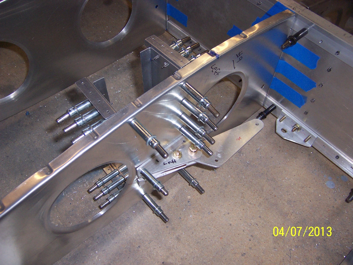
We assembled the left spar by first putting in the AN bolts and screws. Due to our “bolt-fit-obsession” you cannot cleco the parts first and expect the multiple bolts to go through all the layers in the assembly.
Bolts & Screws In Spar First
Added some black clecos and ready to rivet.
We borrowed a 3X rivet gun from a friend who is building a Rocket. Our EAA Tech Counselor suggest to start in the middle and work out to both sides.
We got about 5 rib bay sections done when I had to leave. Dan was able to finish most of the dome head rivets to the tip. Here are some of the rivets:
Dan & I took apart the left hand spar and prepped the parts from priming. Our method starts with deburring, then 3M (of course) 120 grit aluminum oxide sand paper, then 240 grit and a final pass with red Scotchbrite hand pads. It is amazing how many little scratches happen when you handle these parts so much. The long web parts took a while. The spar caps needed a lot of work with all the drilled holes for the webs. I was using the sand paper and it went pretty slow to get the dings out. Later on Dan tried light pases with the vixen file and it worked great, still needs to be cleaned up with the sandpaper but really fast. Oh by the way we use gloves when we sand because the aluminum dust will make you hands really dirty.
We mounted the two vertical C shaped channels behind the aileron bell crank assembly. There are little right angle peices that connect these channels to the skin. All this extra structure is to stiffen the rib where the bell crank is. The plans show to make the top face of the angle peices flush with the curvature of the rib flange, since both are riveted tot eh skin. This took me more time than I thought it might because the rib flanges are not perfectly square, some are a little over bent, so it is hard to tell where to mount this angle bracket vertically. Dan had a good solution to clamp a long piece of aluminum angle extrusion to several ribs on either side of the bell crank rib. The angle extrusion is stiff enough that it won’t bend so it will lay like the final skin on the ribs. With the extrusion on the ribs, I could see the gap of the over bent rib flange, and mate the angle bracket to the under side of the extursion. We think when the skin is riveted on it will pull the rib flange up a little. Once we had the top ones done we moved the extrusion to the bottom as can be seen here :
Locating Bottom Skin Bracket For Aileron Bell Crank
Celco-ed Bell Crank Brackets:
Top Skin Brakets Mounted
We took the wing structure apart do deburr the parts for priming.