Left Wing Landing Light

12/24/2013

After working on and off through the day with a large break for Christmas Eve dinner with the in-laws.  I am about half done with the list I generated yesterday and started the landing light but was confused by the notes from the right wing landing light installation.  The right light appears to be outboard of the design depicted in the Ductworks installation manual.


12/25/2013

Merry Christmas!

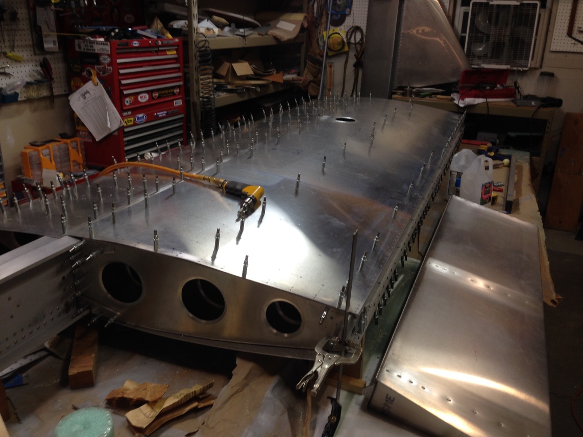
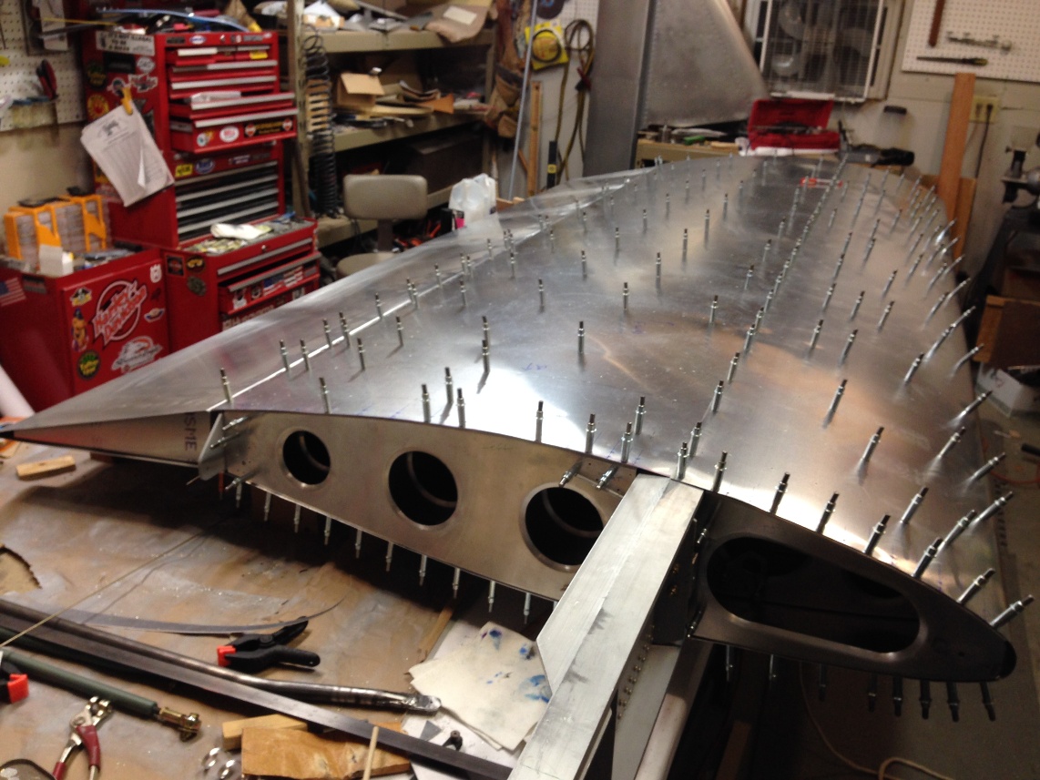
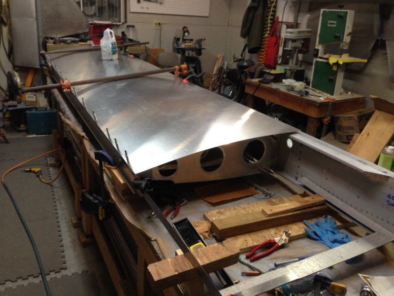
I must have been adversely affected by the Christmas Eve dinner last night.  By the time all the guests left last night and I was back in the garage working, it was at least 11:00 before I finished the aileron and got to the light.  My Father-in-law and Brother-in -law lent a hand to close the fwd skin.  This skin was very tight compared to the left wing fwd skin (as I remember).  I think the difference may be partly due to a little more overlap of the trailing edge of the skin over the spar cap, or it could be the fact that when I match drilled the ribs I had the left the fwd skin under the  aft skin (necessary to match drill the trailing edge of the fwd skin).  As mentioned, I managed to finish attaching the aileron after C’eve dinner.  The aileron required that the counter weight bolts be reversed so the nuts did not risk scraping on the 312 rib flair.
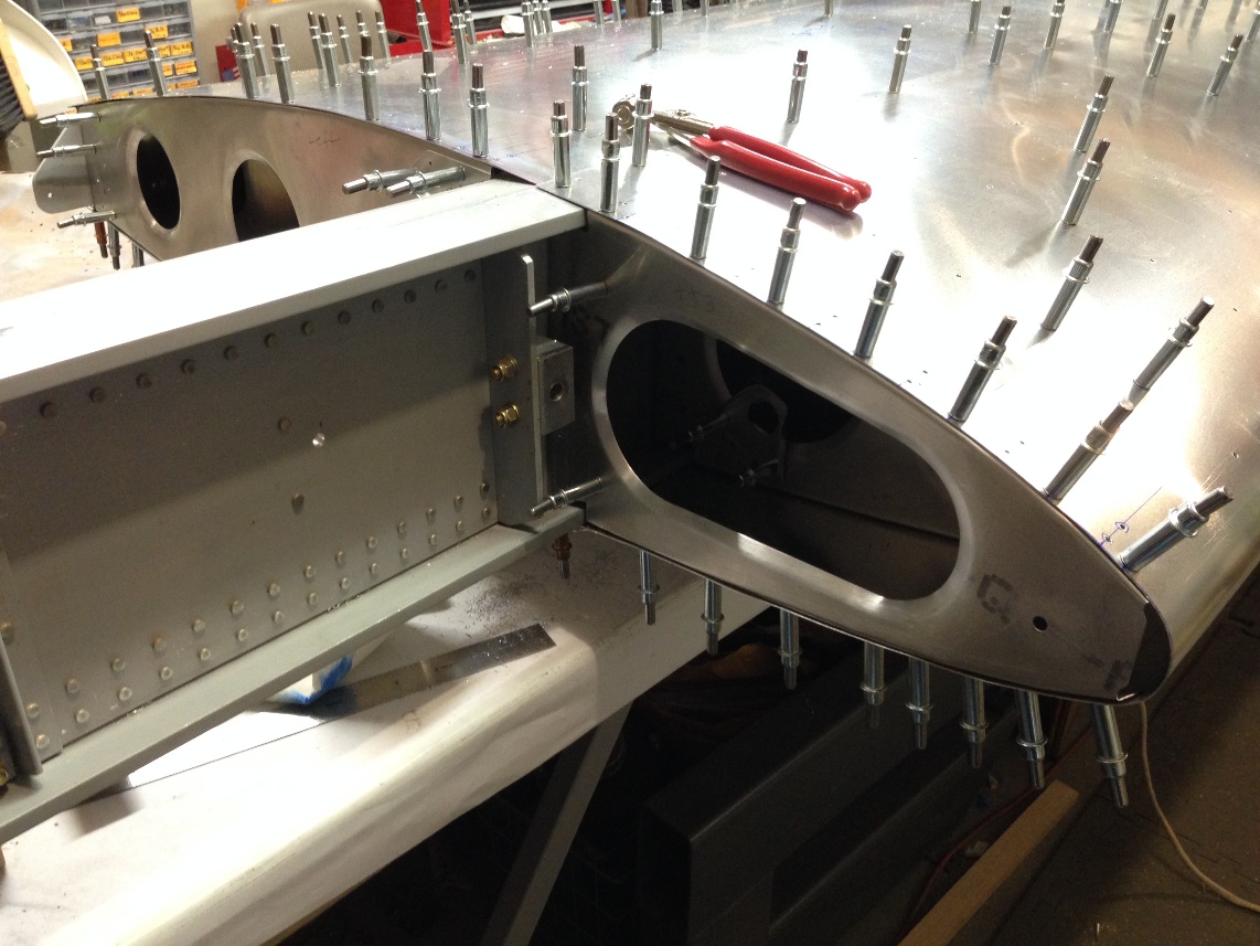
 

Landing light:

The landing light on the right wing appeared to be mounted very close to the outside rib. At least that is what it looked like last night when I was trying to review the installation in the dark garage corner where the wing was hanging.  The Ductworks manual shows the hole biased 1/2″ inboard from being centered between the ribs.  The manual makes a note that the left and right wing have the mounting offset because all the ribs on the plane are oriented the same way (the rib flange is directed inboard on the right wing and directed outboard on the left wing).  This difference between the left and right wing will shift the relative mounting of the reflector by 1/2″ outboard on the right wing. The manual says you “might” want to shift the location of the hole to compensate but then suggests the difference  is not likely to be noticeable.  My thought is that I would move the hole but it’s unclear which wing (right or left) should be moved from the dimensions shown on the plans.  It would be useful to understand what (if any) target distance the light is ideally best to be aimed at.  Understanding this would make it easier to make an adjustment to the hole.

As I understand it, the angle for the right light and the left light are different as on is to be directed for taxi and the other is aligned for the AOA (Angle of attack) during the landing process.  While much of the angle adjustment is vertical, the horizontal angle of the light will change slightly, with the landing approach angle being directed closer to the plane and the taxi light being directed further down the runway (of course, this angle difference may  not be correct for a tail wheel plane as the taxi angle would be roughly the same as a 3 point landing angle and a two point landing or take off roll on a tail wheel would be similar to the taxi angle on a tricycle gear).

I have spent twice as much time thinking about the subject (and writing about it)j as it deserves and I will be installing both wings with the landing lights in the same location.  As it turns out, my initial measurement of the right wing hole (that I installed months ago) was not offset but followed the Ductworks manual so I will do the same with the left wing.

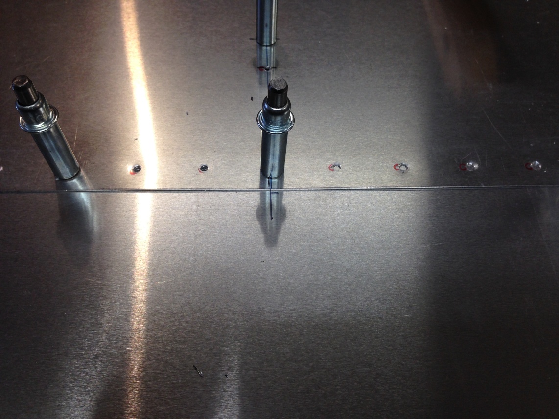
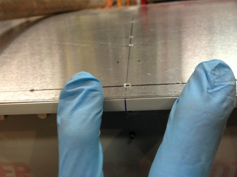
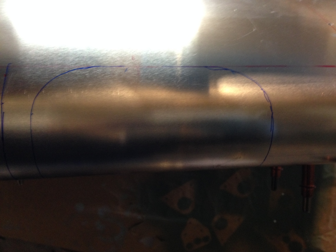
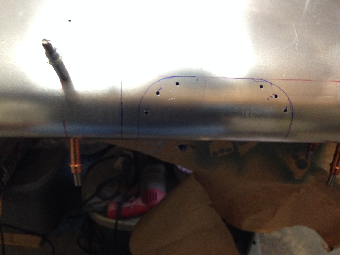
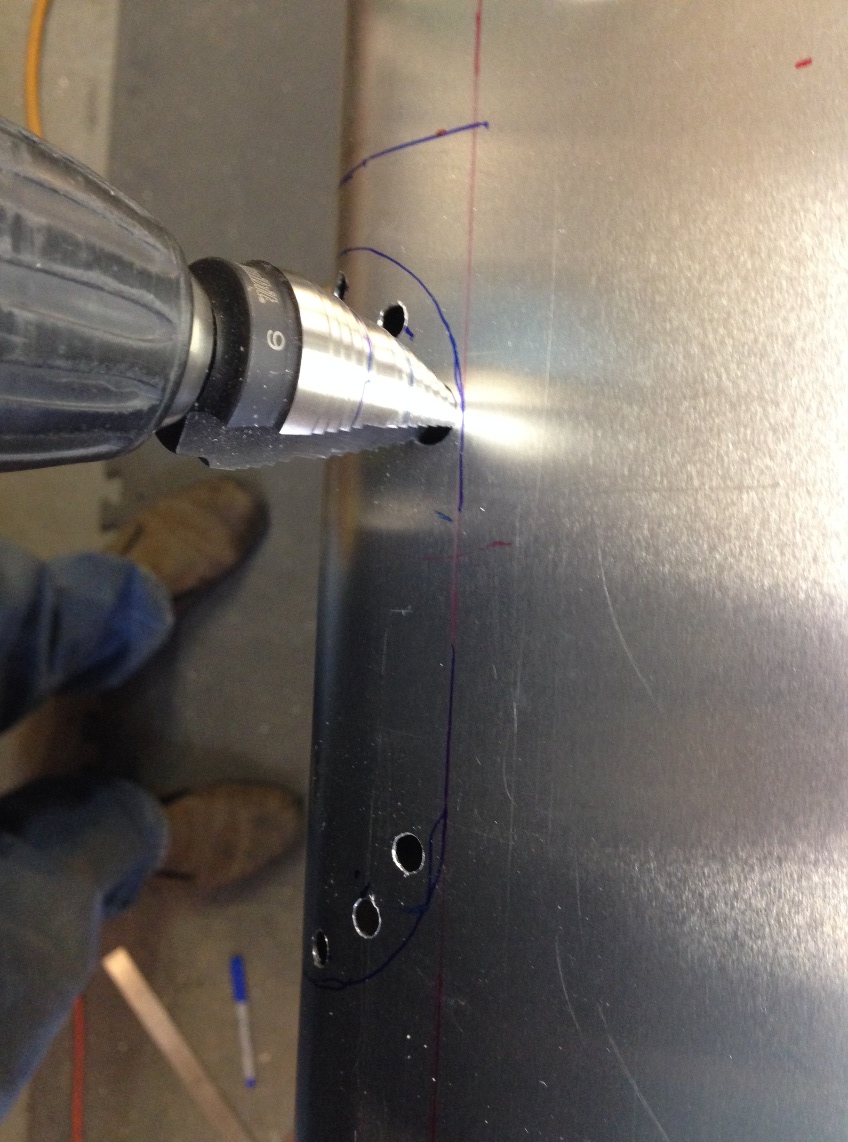
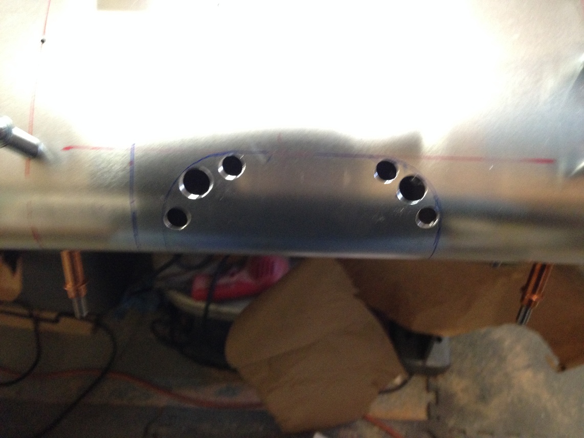
I was able to mark and drill the corner holes for the light and decided to use the nibbler to do most of the cutting for the hole.  I used an abrasive wheel with my Dremel tool on the right wing and it was very unnerving trying to hold the tool steady with visions of having it jump across the leading edge of the wing if it caught the edge of leading edge.  The nibbler may be a bit slower but more relaxing for most of the cutting.  I may end up cutting the actual leading edge with the Dremel but that is about it.

My goal (last year) was to finish the wings by Christmas and a year later I still have not succeeded but I am very close and will likely finish the second wing before the end of the year.  I have to travel to Singapore through most of January for work so not much will get done after the Christmas Holiday so finishing the second wing and having them both hanging by January would be a nice place to finish the year.


12/26/2013

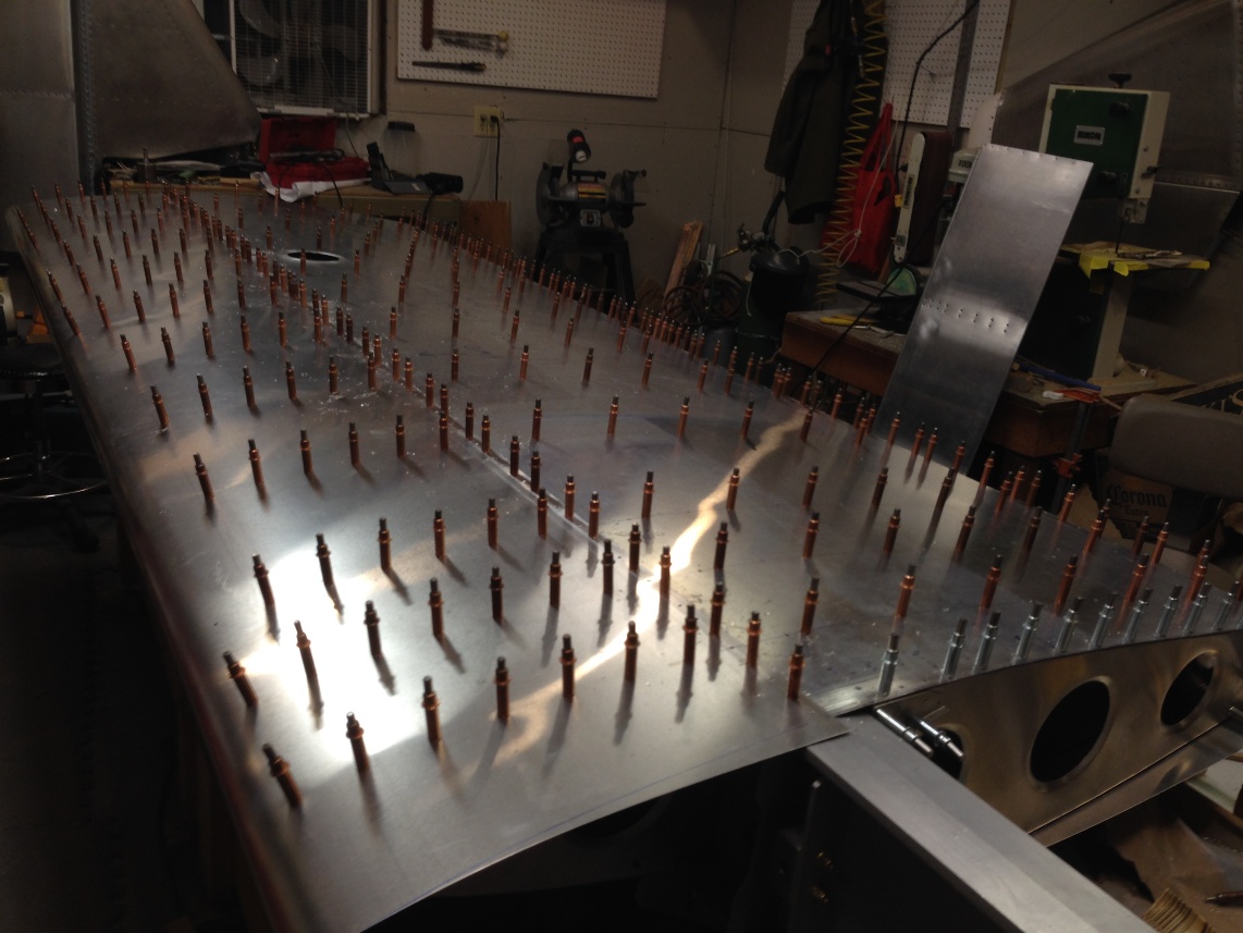
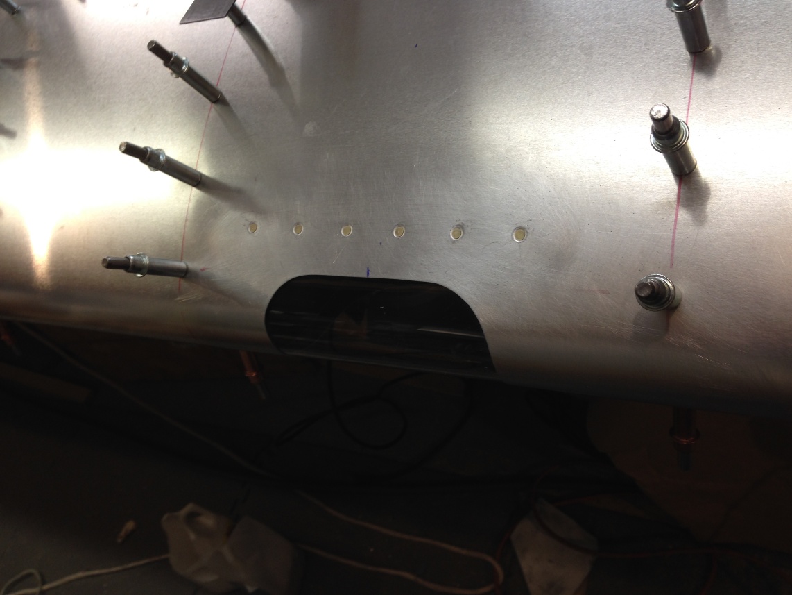
It looks like I might finish the wing if things keep going as they have been.  The landing light installation is completed with the exception of 4 nut plates that need to be install once the skin is off for dimpling. The Ductworks manual suggests that you can install the landing light on a finished wing. I think this is true with the exception of pulling the rivets on the nut plates on the ribs. I’m sure with the right tool it could be done but I tried on the right wing and managed to get the rivet puller stuck and had to remove the rib with the rivet puller stuck to the rivet. On the left wing I will just remove the ribs. Maybe a different puller that did not have such a large open handle requirement when pulling a rivet.

So the second landing light is cut and installed. I would say that all went well except for cutting the plexiglass. I do not look forward to installing the canopy when I have managed to crack both of these little landing light covers while trying to cut them on the band saw.  Yikes !


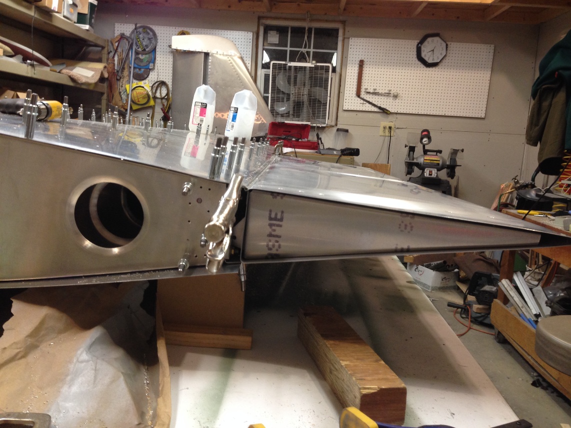
I started to set up for the wing tip next and the only things left after the tip are up drilling the top side, demurring, dimpling, priming and assembly.  Oh ya, there is the root doubler to finish.  That should not be too bad so I will still predict the wing will be done before New Years!

Return To Wings


Left Wing Forward Skin and Flap

Today, December 23rd, I was able to fit the aft root rib, ( I may have done this yesterday), remount the fwd ribs, drill the fwd skin, match drill the fwd skin and then updrill the entire lower skin area as well as mount the flap.

The wing is ready to flip over and finish the fwd skin and then match drilling and up drilling.

A couple other things to do before breaking it down for deburring, dimpleing and priming the ribs and skins as well as CS the spar caps.

I have to fit the fiberglass tip put the 40 nut plate for the  tip. (3 hours)

Fit the aileron (match drill the hinge and updrill) (15 minutes)

CUT THE LANDING LIGHT!!   (6 hours)This is one of those white knuckle jobs that require plenty of care as soooo much time has been invested in the skin and ribs that I do not want to mess them up.

Speaking of messing up.  The one thing I did today, that I caught before going too far, is not realizing that I did not trim 3/4″ off the leading edge skin and proceeded to match drill the skin to the spar.   Some explanation is needed here; the skin is formed with the top and bottom sections cut to 15-7/8″ so the vacuum forming will bend them symmetrically.  After the leading edge is formed, the lower section (half) of the skin needs to be trimmed by about 3/4″.  I marked the line where the trailing 3/4″ needed to be trimmed after it was formed (last spring) but I did not trim it off at that time.  Although I did mark the drill holes and it was these marks that led me to realize that something was amiss.  Fortunately I did not drill any of the field holesIt all turned out well and I only had to redo the match drilling to the spar after trimming the lower section to proper length.

A close call that would have been a real pain to correct. Lucky me.

Return To Left Wing Assembly

Left Wing Bottom Skin Level And Match Drill

Today was perhaps a good example of how quickly things can move along in the assembly process if all the parts are made (like a kit, instead of scratch building as we are) and if we don’t mess around thinking too hard about stuff.

Tim was busy until around 1:30 and I had a load of issues to attend to with regard to work (I so much for vacation but at least I could take care of it without leaving home).   The morning was spent catching up on email and getting things prepped for dinner (gotta keep the “sweetie” happy).  After all that it was almost 12:30 before I got into the garage to even turn on the heat.  I was in the garage actually doing something by time Tim arrive.  I had been on a conference call and simple kept my headset on while on mute and listening in as i drilled holes in the skin to finish the top side match drilling.

When Tim arrived i had the match drilling pretty much done and while I pulled out the bottom skin Tim cleaned up the rear spar trailing edge to file off any alignment error between the skin and the spar.

We flipped the wing over and Tim aligned the bell crank brackets to the upper skin while I worked to level the then skin by supporting each of the four corners with blocks and shims to insure the wing was flat (not having any wash out or pitch variation from root to tip.  

Left Wing Level Bottom Side Up

The process of squaring and leveling the wing (as mentioned earlier) can be done a couple different ways but the bottom line is that (in my view) you need to have an image in your mind of the process you are involved in.  I spent a good part of my youth working for my “old man” building houses and even did it for a few years before and during my college years.  The process of squaring a wall so that when you stand it up it will be plump is very similar to assembling a wing to be square and not have any wash out. For me it is almost an intuitive process that I know most framing carpenters would find easy.

The process can be broken down into two primary steps.  The first skin must set the wing with regard to square (which is not terribly hard but a bit of a challenge to find a reference).  The second step, once the wing is held square by the first skin, is to insure it is flat (no wash out).

To square the wing it is also a good idea to have it close to level, although not necessary to be exact, it will be needed on the second side skinning so the procedure is good practice.  Once level it is easiest to find four points that define a parallelogram. The first two points on the skin are the wing station 22-3/4″ center line at the center of the main spar and the trailing edge of rear spare at the same 22-3/4″.  These two points will be  marked on the upper and lower skin as the intersection of the center line (where the holes are drilled) and the edge of the skin.  If you cut our skin carefully (as you should) the final width should match the plans and the skin should be square (don’t trust factory cut sheets of aluminum to be square).  Even though the root and the wing tip have very irregular contours, the center line of the first rib in from each end (rib #1 and rib #12) should form a perfect rectangle on the wing skin.  The second two points are the same position on theT #12 rib. The key characteristics of a rectangle is that each of the opposite sides is the same length and the angles where the adjacent sides intersect should form 90 degree angles. The wing skin when laying flat provides a perfect pattern to align the wing box.  The only task that remains is to identify the reference point that make a rectangle on the skin, and mark them on the wing box.

To really describe the above process i need to generate a picture or some sort of graphical layout.  maybe that will be a task for later.

Once the wing is held square by the skin on one side of the wing, attaching the second side will give the wing 3 dimensional rigidity.  Holding the wing flat, or vertical and planar, when skinning the second side will insure that there is no wash out in the final wing structure.

If all of the wording above is confusing, I hope it is because of my poor explanation and not the readers inability to understand the concept of square and flat.  Otherwise, you are doomed.

Wing Skin Drill Jig For Between Ribs

The bottom line for the  night.  The bottom skin is fully match drilled and the inspection hole is cut.  Tomorrow I need to determine if I want to add the fwd ribs and skin or updrill the aft ribs.  it probably does not matter but immediately after the leading edge is skinned I will proceed to cutting in the landing light for the left wing. That could happen tomorrow…

 Return To Left Wing Assembly

Left Wing Skinning Top

Left wing skinning

December 15, 2013

The left wing is expected to go much faster than the right as all the parts have been pretty much completed and the right wing assembly included welding the control rods.  In a sense, the left wing assembly should go at least as easy as building from a kit, maybe even easier since the right wing had just been completed so the assembly procedures were well understood.

The left wing box had also been assembled and updrilled to #30 (1/8″) as well but none of the gussets had been riveted and the majority of the ribs were not deburred.  Although the ribs needed to be deburred again after being match drilled to the skins, I was thinking of riveting the gussets to the ribs before assembling the wing.  Plans changed and I ended up working the last two days of the week, contrary to my original plans.  This led to not having all the ribs ready to prime and rivet the gussets so I chose to begin assembling the wing box on Saturday morning.

Tim and I got together on Sunday afternoon and while he finished deburring the missing aft ribs I finished deburring the fwd ribs.  After the aft ribs were deburred and clecoed in place the wing box was leveled, squared and clamped to the bench top.  

Tim and I discussed how many builders skin the wing vertically while I was proceeding as I did on the right wing by leveling and squaring it while flat on the table.  I am confident either would work and any discussion on which might be better might be a waste of time.  I feel it is easier to constrain the wing when it is flat on the table, which is my primary reason for why I would rather have it horizontal on the table.

Anyway, once Tim was comfortable with what I was doing (or tired of going over the procedure verbally) we moved forward and found a location that was as level and square.   We then laid the pre-marked top skin on the box and checked the alignment of the marked hole center lines that were yet to be drilled, with the centers of the ribs.

We then checked the only reference dimension on the prints that provided an alignment for square.  This was the wing station zero point (also the center of the wing span) to the rear spar attached hole.  This measurement was supposed to be 19.0″  The original measurement we checked did not come up to 19 inches  but after a little review it was apparent that there was a bend in both thee main and rear spar that was distorting the measurement.

Tim had to leave and so I had time to drill the top skin and mount it on the wing box.  Mounting the skin provides an easy method to straighten the spar out by match drilling the rear spar, beginning from one end and making sure the trailing edge of the spar was flush with the wing skin.  After this is done the wing can be squared by checking that the centers of the drill holes aligns with the rib centers at the ends (the middle of the ribs are unreliable as they tend to wander a bit until match drilled to the skins).  It is the rib centers marked on the spars that make the best reference for the skin hole centers.

With the aft spar match drilled to the skin the wing box can be clamped at the main spar and the 19″ reference dimension can be checked.  This time the measurement came out to as close to precisely 19.0″ as I can measure.

Left Wing Station Zero
Left Wing Station Zero Ruler Value
Rear Spar Bolt Hole For Measuring Wing Square-ness

I have pictures of the 19″ reference measurement as well as the alignment of the skin center lines with the rib center lines.

A few pictures of the semi finished match drilled skin and wing box and that is about as far as i am going to get tonight.  Tomorrow Tim and I expect to both be able to work on the plane during the day as we both have “vacation to take up” as my friends if Singapore say before it evaporates at the end of the calendar year.

Return To Left Wing Assembly

Right Wing Sling

Right Wing Sling

December 14, 2013

The right wing was done almost a week ago and I have done little on  the plane since then.  Mostly  because work  has really  been taxing at the end of the year and I need to take my remaining vacation or lose it by December 31st.

I am off until the end of the year (at which point I will likely be traveling for the first three weeks of the year for work so whatever I don’t get done through the rest of December will sit until February.

A few small things did get done during the week.  I cleaned out the lower section of my work bench (all 12 feet of it) and moved the aluminum angles off the 12′ rolling material rack. This left room on the rack to hang the complete right wing.  I struggled for a few days after the wing was completed trying to come up with an elegant method to store the wing.  I wanted it secure and safe but still be relatively easy to get at for reference while completing the left wing.  I came up with using a canvas tarp and with a few simple ropes making a sling that I could either hang on the wall or as I alluded to above, hang on the back of my material cart.

Slipping the wing into the sling was a two man job and Tim was able to stop over Wednesday night after work to lend a hand.  I have a few shots of the tarp with and without the wing on and I think it worked out pretty  well.  I have a better idea for the next wing, which is to buy another tarp and secure the tarp around the wing while the wing is on the bench and provide a rope handle to simple pick up the wing near the center of gravity.  I could then just carry it over to where I want to  hang it and hook the handle on whatever I have decided will work best (a set of hooks on the wall or off the material rack).

So, my goal for the next two weeks is to see if I can assemble the left wing and get it hanging on the wall before I have to return to work.  Tim had a couple days off last week where I was stuck finishing things up for the year end and i know he was dying to come over (while his kids were still in school and he had time off).  Hopefully this coming week will work out better and we can make some real progress with two of us in the shop.

Left Leading Edge
Left Wing Walk

We might add a wing walk to both sides if we modify how the canopy opens.

Return To Right Wing Assembly

Main Spar (right)

So many small details that we have documented with photos and emails back and forth but so few posts on the web site.  We need a secretary….

In November of 2012 the right wing box was assembled for the first time and in December and January (2013) the ribs were match drilled to the spar, up drilled and the gussets were attached.  Many web sites (Blogs) keep track of hours meticulously but we are really bad at it.  I (Dan) try to spend some time each available day in but there are many days that do not allow any time to work on the plane.

Regardless, in late January everything was in place to begin assembling the right spar.  Counter sinking was done, dimpling was done as well as de-burring and light priming.

On Monday night I drove the first few (flush) rivets on the right spar.  They turned out pretty good but we are using conventional riveting with a pneumatic rivet gun (3x borrowed from Gary Hall, our Harmen Rocket builder friend) and bucking bars.  We found the quality of the flush rivets was very good when using the conventional method with the proper counter sink depth.  I wrote up a little analytical evaluation of the countersink calculation that seemed to be pretty reliable.  The bottom line is that for a 110 degree countersink and 0.032″ skin, an AN426-AD-5x rivet required a minimum of 0.022″ more diameter countersink than the rivet head width at it’s widest.  I will have to post the calculations but the rivet head is 0.275″ wide so the counter sink needs to be in the order of 0.300″ diameter.

Counter sink diameter

After driving a small number of rivets it became apparent that this job would be much easier with two.  So the following night, Tim and I got together and started driving rivets.  As was expected, we got progressively better at it as each rivet was driven.  That was until we go to the section of flush rivets on the spar where the rivets are buried between the upper spar cap and an angle brace.  Our best efforts resulted in driving a couple less than ideal rivets and drilling out most that we put in due to them being dumped on the shop side.  We debated back riveting (putting the flush head against a smooth metal surface and driving the shop end with a hammer and bolt like Sonex advocates)  these are hard to get at rivets and eventally decided to sleep on the issue.

Return To Wings  – Main Spar

Cutting oval holes on W13 parts

The following series of photos shows the steps we used to cut oval holes on the W13 parts.  The photos need little explanation.


Center of offset circles to make up the oval


Clamps and clecos with aluminum scrap below to keep part in place while drilling

First hole complete


Drilling the second hole


Second hole complete


Skipped a bunch of steps but photo of finished W13-01R part

Return To Wing – Rear Spar

Wing rib (aft)

The Sonex workshop (no charge to attend when you buy plans) provides a good opportunty to form a wing rib.  The difference between the workshop and making one in your garage (hanger or basement) is that all the preparation is completed in the Sonex workshop and need to make all the preparation and associated decisions in your garage.  And, most importantly, the rib you make at the Sonex workshop will not go into the plane you are building.  In reality, builing ribs is one of the easier tasks of scratch building.  It’s just that there are enough of them (52 total on the wings) that you really want to follow a path that is efficient and produces a quality part.

The starting point for the rib, is of course the rib former.   We purchased the rib forming kit from Sonex.  The most obvious thing you notice when you inspect the kit upon delivery is the fact that the user (that’s you) needs to make the second half of the formers.  This is not a big deal as you can easily pick up some particle board (3/4″ or 5/8″) and trace out a backup former (the manual calls it a “crush plate”).

If you read the outline of steps in the documentation provided with the plans (SNX-W15.1) mentioned above, the procedure instructs you to cut the crush plate approximately 3/8″ smaller than the form block.  This point is interesting because I don’t recall the crush plate we used at the workshop being smaller (I’ll admit it might have been smaller and I simply did not notice) and all the form block sets I have made from scratch for the horizontal and veritcal ribs have been matched sets (i.e. no 3/8″ smaller size for the crush plate).

I can see advantages to both making it smaller and having matched form blocks but I thought that I would build one rib with the crush plate made full size and see how it turns out.  I could always cut it down to the 3/8″ smaller size.

The rib former set is shown (above) before the fluting grooves are added to the new form block.  The lighter colored block is the one from Sonex and the darker is the one I made.  The difference is the Sonex block is from particle board and mine is MDF (medium density fiberboard).  The MDF provides a smoother surface to bend parts on but it is a MESS to cut and sand.  Both will work.

Cutting the rib blank is the first step and as has been documented in numerous web blogs, there are multiple alternative methods to cut blanks.  The simplest is to use a washer to trace out the blank around the form block.   The oveall procedure is:

1) Rough cut a “rib blank” slightly larger than the final size needed (approximately 1/2″ or more larger than the rib former dimensions, on all sides)

2) Drill the 1/4″ holes in the rib blank , using the former as a drill guide.

3) With the rib blank located between the two formers and held in place with the 1/4″ bolts that pass throught he formers and the blank, use a sharpie to marke the rib blank outer edge to be cut (use a washer with a 1/2″ material width between the inner hole of the washer and the outer diameter to guide the sharpie).

I found that once marked and rough cut, I could trim the rib blank very close to the marked line with a band saw and then using the vixen file to trim the edges followed up with 120 grit sand paper to smooth out the file marks.

The alternative of making an oversized pattern out of your favorite scrap material and using a router to cut the blank to size is something to be considered.  Since there are 26 of these blanks to cut it could be a time saver in the long run.  In particular, the corners could be cut much more quickly with the router method and trimming and de-burring these corners takes more time than the entire perimeter.  Obviously, whether cutting with the band saw or using the pattern and router method, a lot can be gained by cutting more than one rib blank at a time.   Using the router method would amplify the advantage with regard to the time it takes to finish off the corners (drilling, trimming and filing the corners takes a lot of time)

The next is to cut the lightening holes.  Again, some have done this as part of the router cut process.  It takes some care but it is not at all difficult to do this with a flycutter and a drill press.  One thing I noted is that on the aft rib I had to use the larger of the two drill presses in the shop (Tim’s).  The smaller cheesy “Tool Shop” drill press (mine) did not have the distance needed from the support post to the drill mandrill and the blank could not be drilled far enough in to reach the proper location for the 4″ holes.

No photos of the rib blank just before forming.

Rib forming is pretty easy on the large ribs on the wings (as compared to the ribs for the vertical and horizontal stabs).  I have found that using the fluting plyers to just start a flute prior to forming seems to help.  After forming all four sides the removing from the form blocks the rib takes on quite a bend (as shown in the blurry photo below).

The standard process of carefully increasing the flutes to straighten the sides along with pressing the rib flat down on the bench with your hand (flanges up, of course) and tapping the flanges until they are at right angles to the plane of the bench.  I adjust the flutes slightly to straighten the flanges and then flare the lightening holes before going back and working the flutes again to get the rib to lay flat.

The entire rib forming process (after blank is cut, de-burred and the lightening holes added) was about 20 minutes max. , which included flaring the lightening holes.  I’m sure this time could be reduced (maybe I did not keep track of my time well and it was less) but even if you could get it down to 10 minutes per rib, with no breaks it will still take over 8-1/2 hours of straight work to form all 52 forward and aft ribs for the wings.    And that is after they are cut and deburred.  Kind of makes buying the ribs from Sonex seem like a deal.  But then again, we don’t do this to make money but rather to enjoy the process of learning and doing.

Return To Wings – Ribs