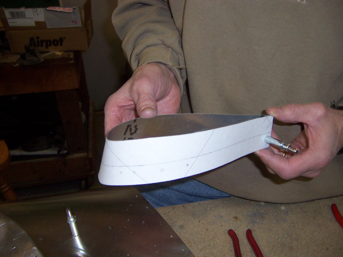
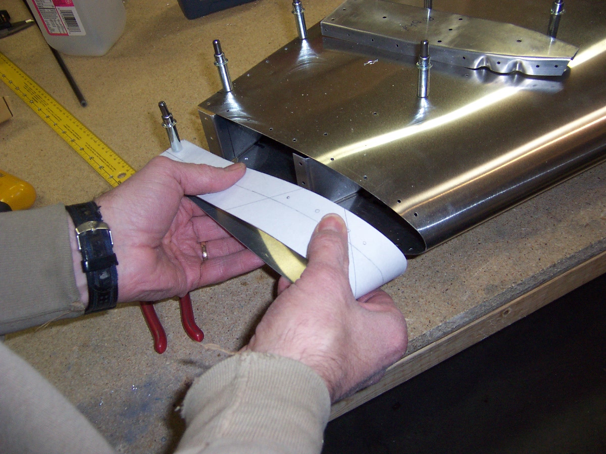
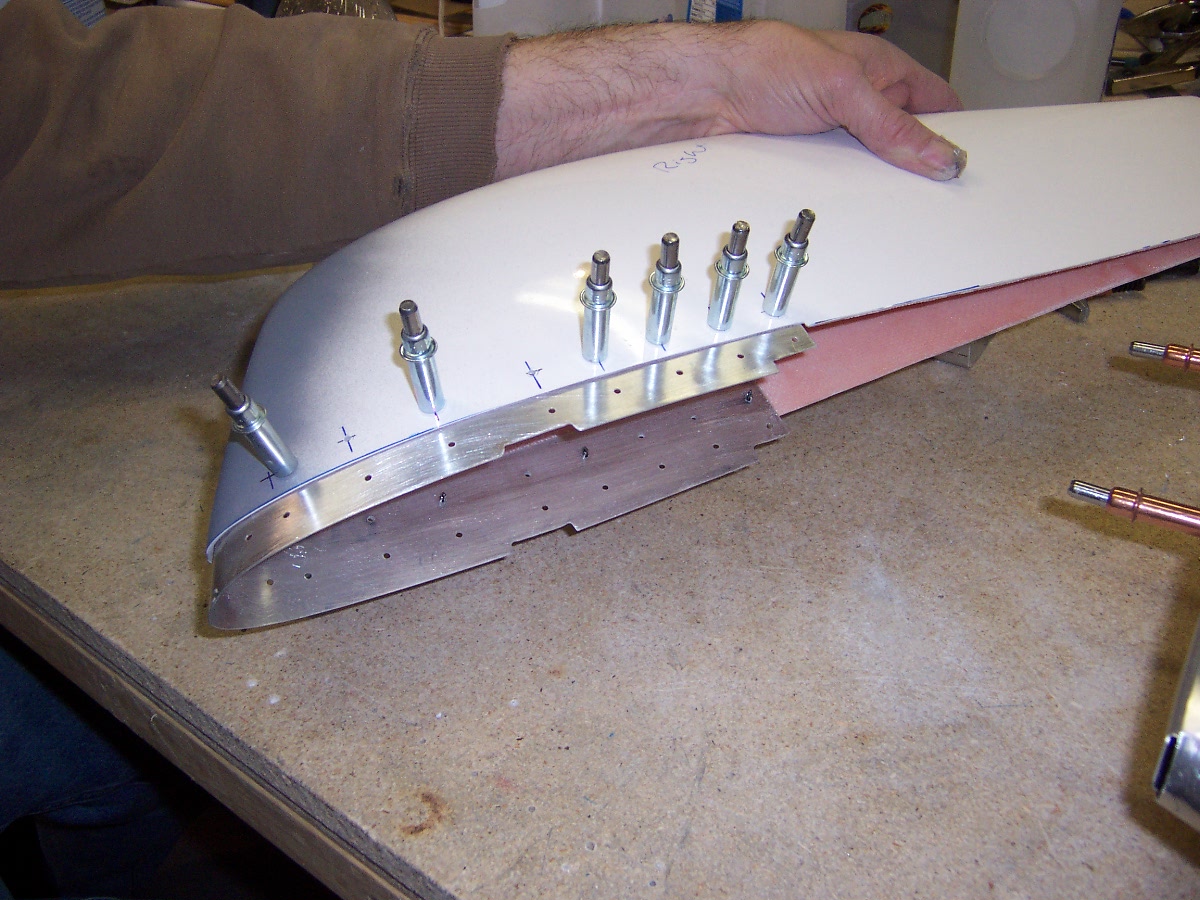
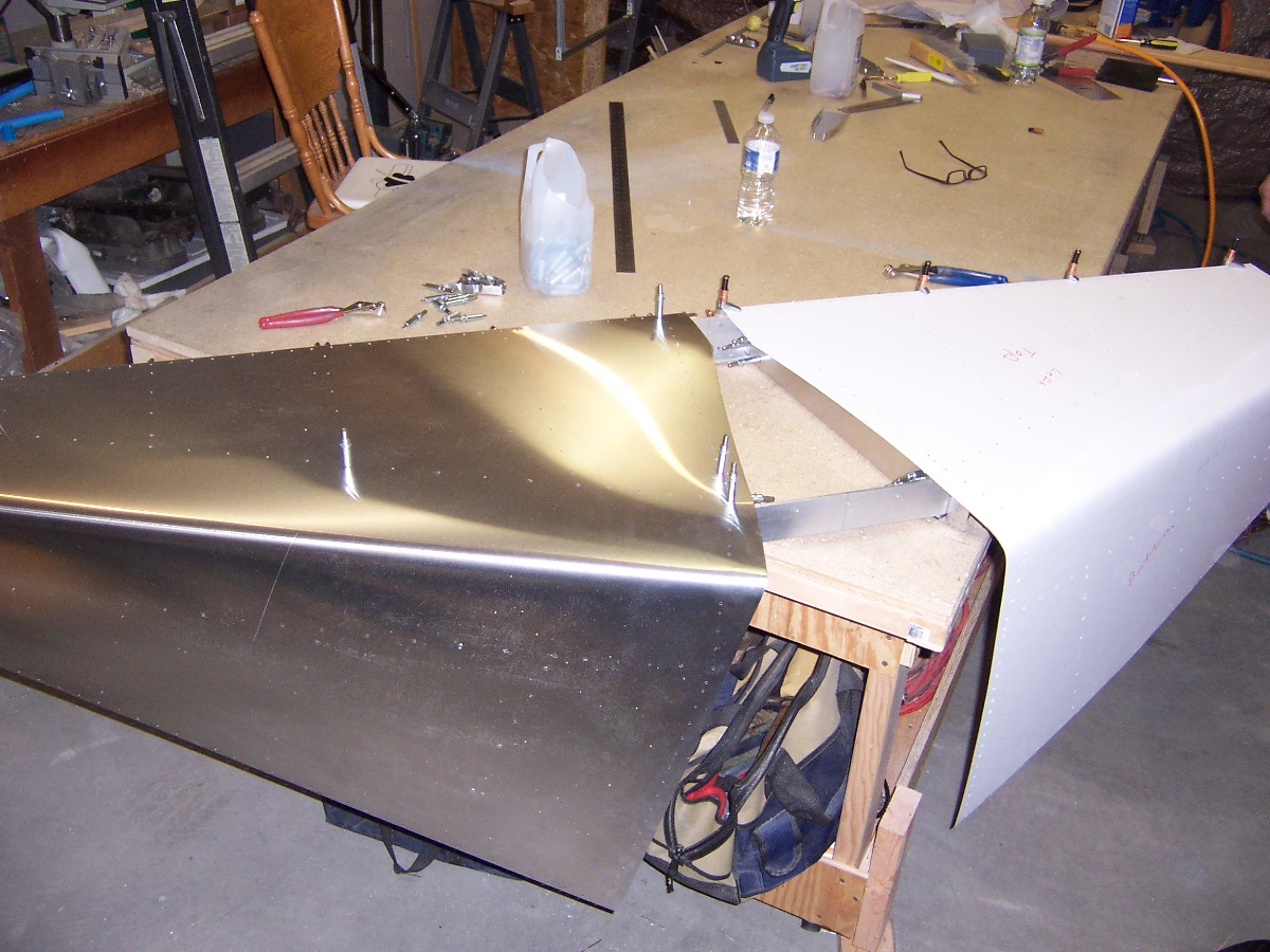
Dan used the same method from the vertical stab tip for the horizontal tips. However we decided to rivet the tips since we don’t think we will need to pull them off. So Dan created a strip of sheetmetal that mounts between the skin and the frame and extends out under the tip.
Horiz Stab Tip Splice Strip
Fitting Tip For Trimming
Measurements For Trim
Trimming With Dremel
Still toook a lot of fitting and sanding
Splice Strip In Tip
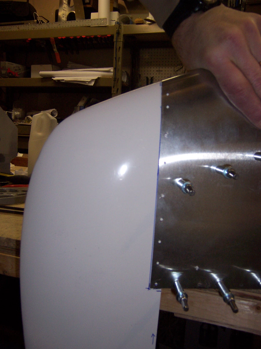
Test Fit Tip
Notice we have a butt joint of the tip and the skin. The plans have the tip slip between the skin and the outboard rib.
The date on thsi if between March and May 2011. We had created a CAD model of the horizonatal stab skin. The plotter has 36″ wide roll of paper and the part is begger than that. So we had to split the drawing and put alignment marks on them to mate them. If you read the Vertical Stab skin drawing entry, you know we were having trouble with the plotter accuracy over a few feet, and also the paper changes dimensions with humidity. We tried out best with the alignment and then wrapped the paper around the frame. With a light we could see where the skin holes were with respect to the center of the ribs. Some were excellent but towards the outboard side it was off a little.
Horizonyal Stab Skin Drawing Wrapped on Frame
We used spray adhesive (3M 77, let it flash off a while before mating) to adhere the drawing to the sheet metal and snipped it out and filed it to the line. Dan measured and used the yard stick jole template to put the row of holes on each side. We then clecoed the tedges together (using those two rows) and to the table. We bent the leading edge using a piece of wood along the length.
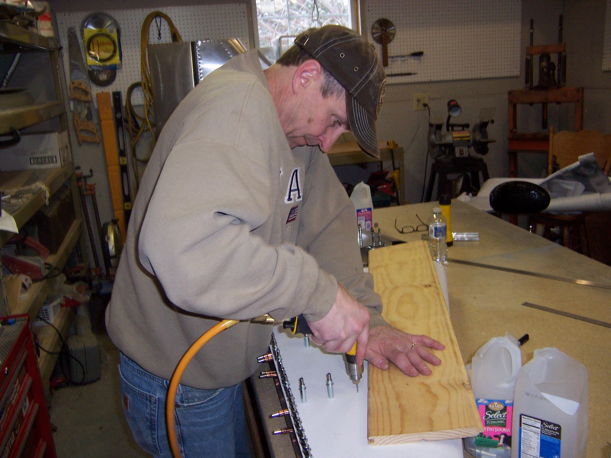
We then clamped one edge of the skin to the frame (took a while to get it right on) and match drilled the frame from the skin. Now the top side we had to match drill the hinge too, so we had 3 pieces we were trying to align perfectly: the skin, the frame, and the hinge. (On a side note we anted to make sure the two seperate hinge pieces were aligned to each other, hmmmm.) Now we could cleco an edge of the skin to the frame and use a pen to mark on the inside of the skin where the ribs are located. In some of the following pictures you might be able to see these lines. Now we could make sure the skin holes would be in the center of the ribs. He did this for the top and the bottom of both skins. Here is Dan drilling out the marked holes
Drilling Horiz Stab Skin Holes
Match Drilling Frame From SkinHorizontal Stab Skins Clecoed On Frame