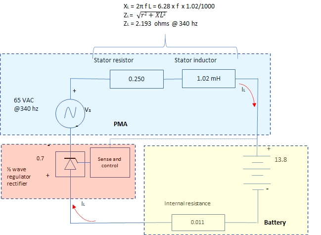
The PMA can be modeled as a simple voltage source with series resistance and inductance components.
R2300 stator electrical parameters – 5 coil assembly (new)
0.060“ copper magnet wire 155C temperature rating, solderable.
52 wraps per coil = approximately 177” of wire per coil
(40 wraps on a burned coil from Glen Bradley)
Resistance: 0.250 ohms[1]
Inductance: 1.020 mH [2]
Open circuit voltage 45 volts (RMS)/ 65 volts (peak) at 3400 rpm (340 Hz) (Hesperia test)[3]
Short circuit current 15.1 amps (peak) at 2500 rpm (St. Paul test)[4]
Voltage constant for
alternator is likely somewhere between 17 and 22 (peak) V/1000 rpm.
[1] Measurements for resistance were done with two different methods on two different stators. The first measurements were taken using an injected DC voltage while monitoring current through the stator. The DC voltage drop vs measured current was taken over time and performed on an “old” stator that had one side of the generating coils burned (the unburned 5 coils were measured). DC resistance measurements on the old stator showed 0.250 ohms at 68 F and rising to 0.337 ohms at 201 F. The second method for resistance was done with a frequency injection at room temperature using the Stanford Research Systems SR715 LRC meter. Resistance for a new coil was calculated from the value of “Q” at 120 hz, where Q = ωL/R.
[2] Measurements for inductance were taken using Stanford Research Systems SR715 LRC meter. Inductance measurement calculated at 120 Hz and 1 volt signal, as recommended in the SR715 manual. All measurements were taken as “series” as opposed to “parallel.”
[3]Revmaster (Hesperia, CA) reported 45 volts with a meter reading as an open circuit voltage at 3200 rpm. It is unclear if this is an RMS reading or (more likely) an average voltage reading, often reported as AC voltage on many hand-held DVOM. Note, RMS voltage = 0.707 * peak; average voltage = 0.637 x peak voltage.
[4] My bench unit for testing open circuit voltage and short circuit current uses a “salvaged” rotor provided from Revmaster, due to the difficulty of obtaining N35 magnets (all available are needed for engine manufacturing). The rotor magnets appear to be compromised (damaged) likely due to heat from welding of the stator. As a result, open circuit voltage could likely be depressed, as compared to a typical field alternator. Short circuit current can be calculated from known inductance, resistance and open circuit voltage, as will be shown later in this document. Short circuit current was across a 3 mohm resistor (0.003 ohms = 100 mvolts @ 30 amps).