April 7, 2012
We recently bent the rear spars with “Big Bend” brake so we wanted to bend the aileron and flap skins. We decided to build the aerobatic ailerons, they are a little wider and hence the flaps are a little shorter. This makes the aileron and the flap close to the same length which is easier to make with the brake.
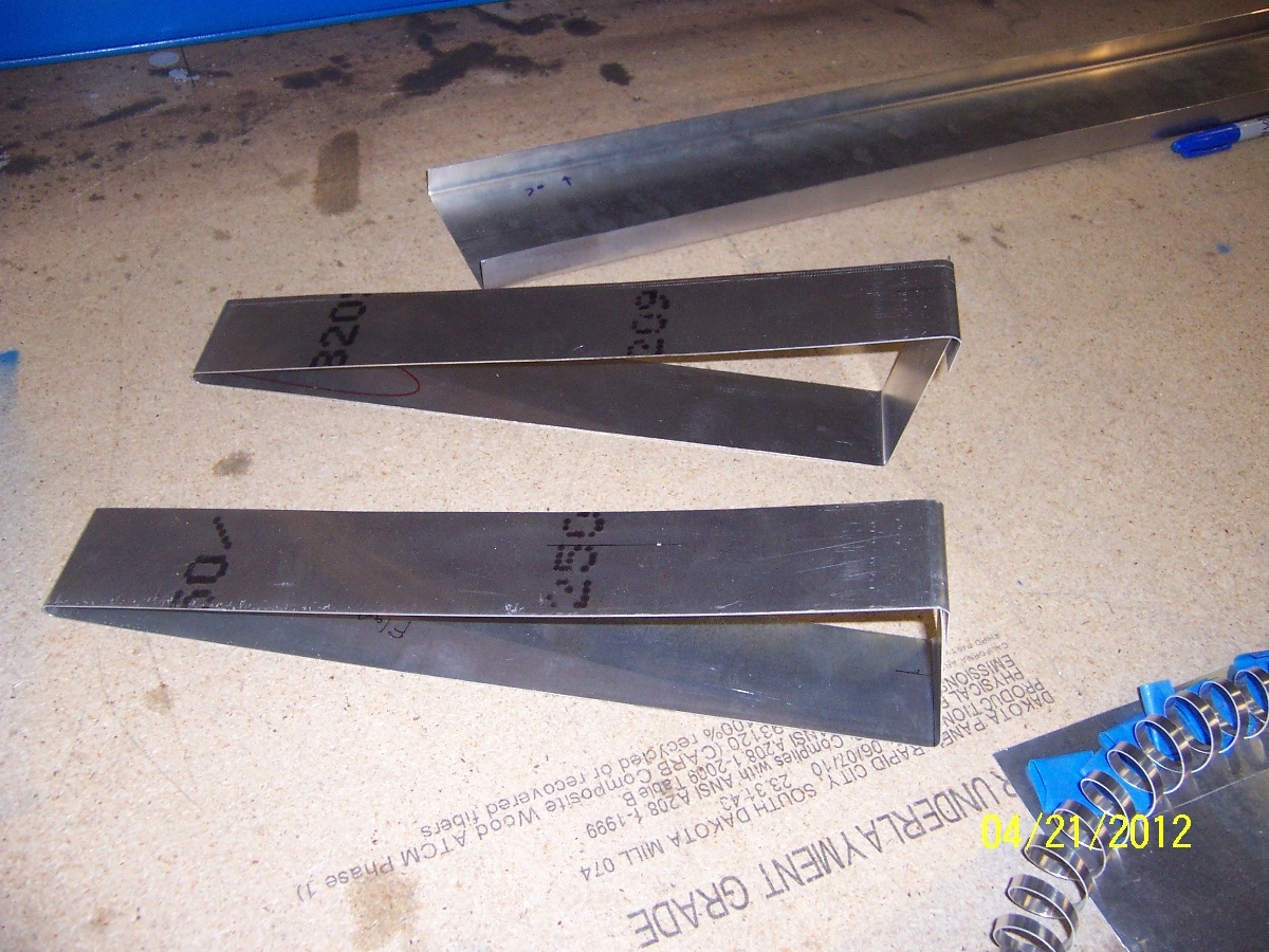
Using a CAD program at work I was able to generate the flat pattern of the aileron and flap. We were able to dimension the tangent lines and the sight lines of the bends. We made some test bends with narrow strips to check the dimensions. The first ones may have slipped in the brake but the second try turned out great.

Since these parts have a 160~170 degree bend at the trailing edge, the sheet metal runs into the vertical leg of the top steel angle when using the brake as it is built. See the picture below

We wanted a really good bend on the trailing edge, and from the rudder experience we would need to bend a full 180 degree with the sheet metal spring back. We bought a 1/4″ thick plate of steel and grinded/filed a bull nose in it so we have our 1/8″ radius on the front.


We bought the steel from a local metal supplier and found it in their “drop” section. These are pieces left over from other cuts and the price was really go. I think the part is 1/4″ thick x 5 1/2″ wide x 55″? long. When we replace the top angle on the bending brake with this flat part we can get a full 180 degree bend. We had to match drill it to locate it to the existing brake assembly.
Using the sight lines we located the skin in the brake.

It is tricky to accurately locate the sight line looking straight down at the tangent point on the bull nose of the angle.

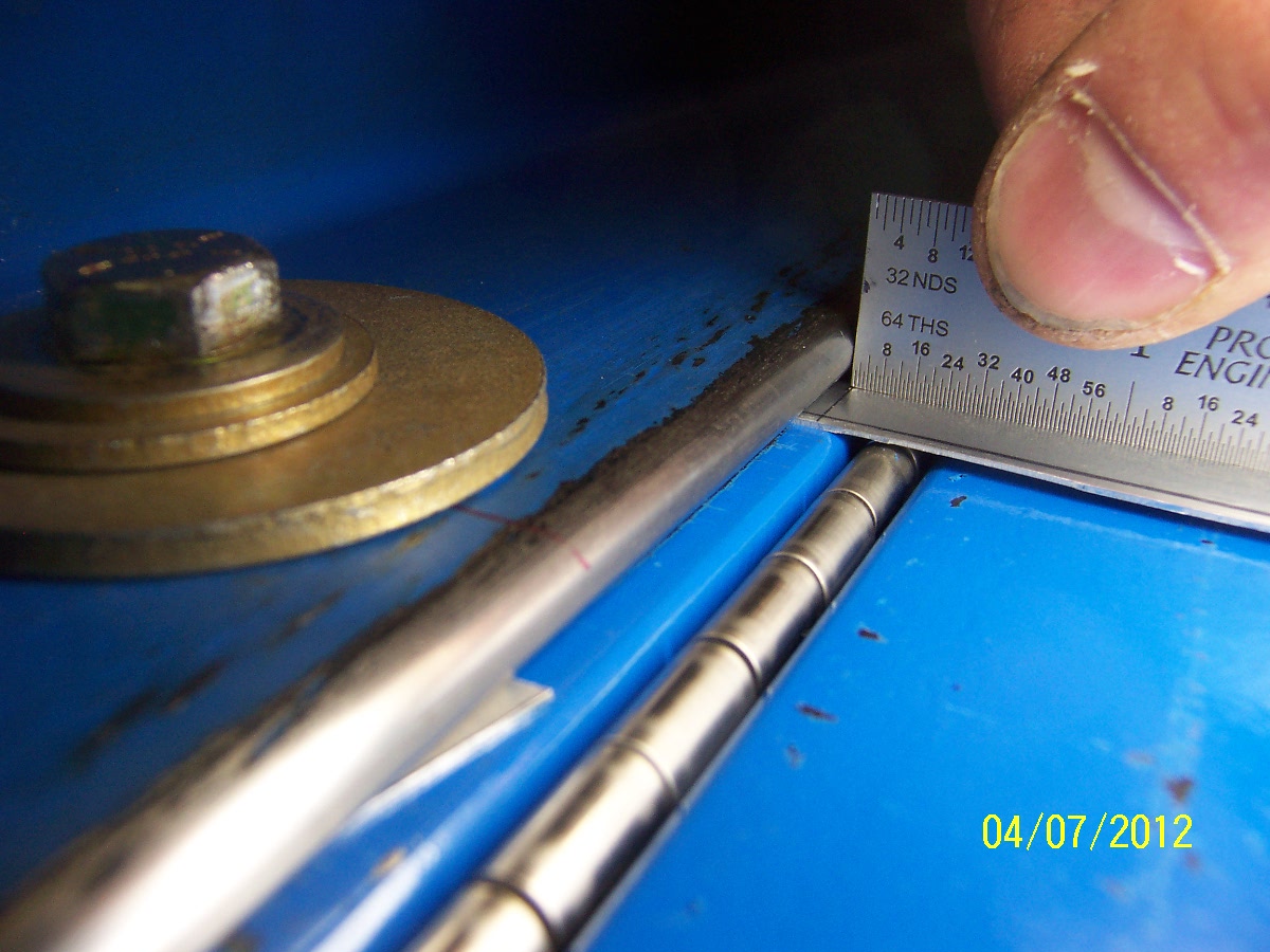
We use a steel rule against the tangent point to locate the sight line on the sheet metal. (Notice the shim on the left side of the bolt, the shim is the same thickness as the sheet metal.)

To get as much stiffness on the top angle of the brake (to prevent bending) we jammed a 2×4 between the angle and the ceiling.

For the trailing edge we would make the first bend to ~90 degrees with the standard brake design. We clamped an angle to the brake to bend it until the skin hit the vertical leg of the top angle.

Now we switched the brake’s top angle for the flat plate with the bull nose. We nested the partial bend into the bull nose, clamped it, and pushed it to the ~180 degree point. With the spring back it came out really well.

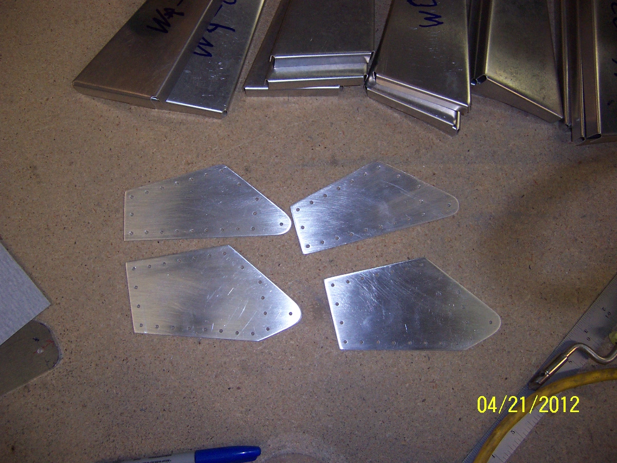
Here is a picture of a rib sitting the formed skin
![04102012398[1]](http://sonex1362.com/wp-content/uploads/2012/04/041020123981.jpg?w=300)
We are really happy with the results.
Return To Wings – Ailerons Return To Wings – Flaps


![04102012398[1]](http://sonex1362.com/wp-content/uploads/2012/04/041020123981.jpg?w=300)


