Turtle Deck Cut Out + Seat Sling

February 23, 2014
Turtle Deck Cut Out & Seat Sling

The turtle deck sections were marked and cut without incident last week. The only issue I had at all was that the power went out do to a massively wet and heavy snow storm on Thursday night.  The total snowfall was only 12 or 14 inches but it started as a rain and snow mix and by the time  the air cooled and the snow really began to accumulate the trees and power lines were loaded with ice and snow.

Turtle Deck Marked Out

The plans do not mention it but I am planning on match drilling the seam at the top of the turtle deck with the two sections laid flat to insure the holes line up. It seems obvious as I write this but the plans show two halves being drilled as separate pieces and only later laid flat to be riveted with the seam channel. The two sections I am referring to are F20-06 (R and L) and the seam channel is F20-07.

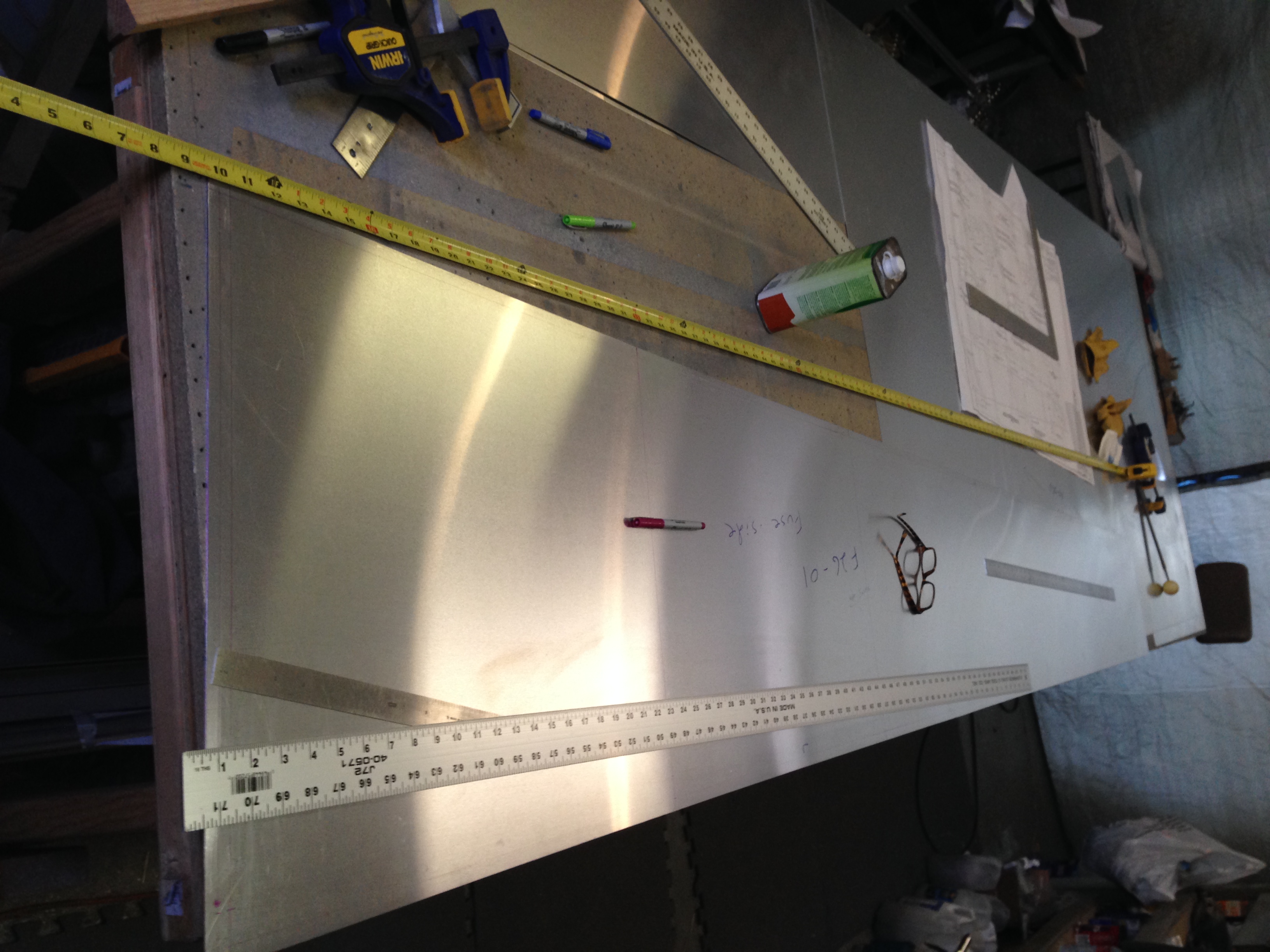
After the turtle deck sections the next largest uncut fuse piece was the cockpit floor, F16-01. This was to be cut from 0.032″ but there were two more pieces needed at 0.025″, the aft bottom skin (that needed to wait until we picked up one more sheet) and then the seat sling. We were planning on installing the sport trainer controls (center brake, flaps, throttle, etc.) and the lowered seat option. Together these two options required we follow C06 through C09.

There a bunch of changes and substitutions related to these four sheets and it is best to carefully read and then review the implications of the sheets. Tim and I are slowly getting up to speed with these sheets and I’m sure by the time we’re done it will seem very straight forward but for now it is often confusing.

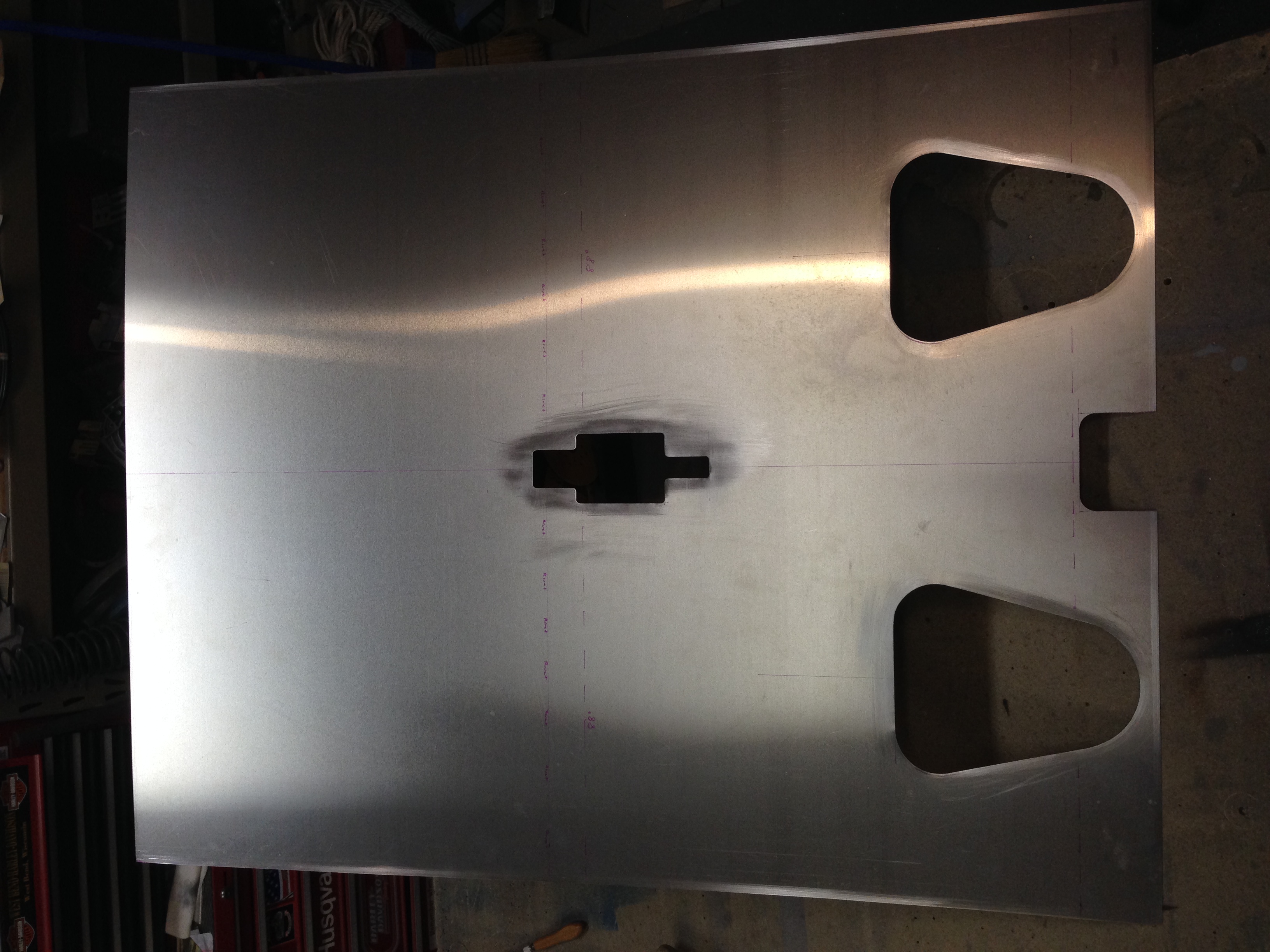
I finished the modified seat sling cut out tonight. I then moved the last full 4’x12′ sheet of 0.032″ sheet aluminum to the table to be cut into the lower side panels, F13-01, lower cockpit skin, F16-01, glare shield and control panel. We need to be sure we have a large enough piece for the control panel to add a few inches to the bottom as others builders have done for a little more instrument room.

Return To Fuselage

Rear Fuselage Side Panels

2/8/2014

Starting the layout of fuselage parts. The plans has the side panels as the highest numbered sheets. Tim and are expecting that we will be at least one sheet of 0.025″ aluminum short. This is due to (likely) some careless cutting on my part, way back when we were fabricating the control surfaces. At that point it appeared as though we had at least one sheet of 0.025″ surplus and when I was cutting out the control surfaces I simply continued cutting them in sequence from a single sheet. The general rule of thumb for consuming sheet goods for best material use is to cut (or lay out) the largest pieces first and to nest the next smaller sized pieces within those larger cut outs. By ignoring this rule and in addition, having to recut one aileron due to a mishap during trimming (grrrrr) I likely set the stage for needing to make another trip to the local aluminum vendor. Lucky for us there is a local vendor for 6061 or I would be paying for shipping.

So Tim and I laid out the large pieces for the fuselage and it is clear we are at least one short. I would say that the fuse parts require the same level of attention to the plans as all the rest. I read through the F26-01 skin multiple times before I realized I missed the detail at the skins are mirror images except for the inspection hole AND the hole for the rudder control slot. I have the two skins stacked to lay them out for drilling and fortunately caught this difference before I drilled any holes.

I think the best procedure is to cut out and complete fabrication and drilling of all the major fuselage skins before heading out to pick up the needed additional sheet as there is little room for error on the large parts before we would need to add to our order. Hopefully that will not be necessary.

Return To Fuselage


Left Wing Final Assembly 3

Final riveting of the left wing.  Funny side note: When you set a pull rivet the stem comes off and you have to make sure it comes out of the rivet gun.  When doing a wing skin there are lots and lots of rivets. So we would set one, tilt the rivet gun, the stem will fall on the skin and roll down the skin onto the work table.  If you are not careful a stem will roll into the open structure of the wing and they can be tricky to see.  As you are probably thinking, we checked and double checked but once the wing was finished and we flipped it around on the bench, sure enough we heard the rattle of a stem in there.  Dan and looked at each and had to laugh.  We will have to fish it out later.   Another side note: we forgot to torque the tie down bolt with the structure open.  We will have to get the torque wrench in there somehow.  We are really happy to have the wings finished.


Now onto the fuselage!

Return To Left Wing Assembly