Welding Control Rods Bolt End Style

Dan has some experience with ox-acetylene welding.  He purchased a new small tip.  We had purchased a bunch of left over drops of 4130 tubing from Wicks to practice on.  I cannot find this item on their website right now.  Dan tells me that the thicker tubing is easier to weld.  The thin wall sizes are tricky since you can melt a hole in the tube if not paying attention.

One end of some of the control rods have a Grade 8 bolt welded into the tube.  The tube is cut so tabs can rest on the hex head faces.

Turtle Deck Ribs Finshed

Dan finished up the turtle deck ribs.  Some of the flutes are hard to get right.  They need to be in the right location to avoid the rivets yet deep enough to make the part flat and the flange at the right angle.  The smallest rib, F20-04, was tricky.  We have the large red fluting pliers and the smaller style.  I want to ask our Tech Councilor about this the next time he stops by.

Dan broke out the “Big Bend” brake for all the fuselage parts.

Return To Fuselage

Glare Shield + Rear Fuselage Bottom Skin

Since we are trying to make the best use of the aluminum sheets we continue to cut out the largest parts first.  Here is the glare shield, F07-01.  We are not sure if we want the sloped instrument panel or a vertical one so we added material on that end.  We can decide later.

Glare Shield

The rear fuselage bottom is the next large part.  Dan used the side of the aluminum sheet but gave a little offset. (Using the electric shears.)

Rear Fuselage Bottom

Here is the finished tail end of the bottom skin:

Return To Fuselage

Left Wing Final Assembly 3

Final riveting of the left wing.  Funny side note: When you set a pull rivet the stem comes off and you have to make sure it comes out of the rivet gun.  When doing a wing skin there are lots and lots of rivets. So we would set one, tilt the rivet gun, the stem will fall on the skin and roll down the skin onto the work table.  If you are not careful a stem will roll into the open structure of the wing and they can be tricky to see.  As you are probably thinking, we checked and double checked but once the wing was finished and we flipped it around on the bench, sure enough we heard the rattle of a stem in there.  Dan and looked at each and had to laugh.  We will have to fish it out later.   Another side note: we forgot to torque the tie down bolt with the structure open.  We will have to get the torque wrench in there somehow.  We are really happy to have the wings finished.


Now onto the fuselage!

Return To Left Wing Assembly

Left Wing Priming 2

2014_1_2

Tonight I was able to squeeze in a couple hours priming before my 9:00 call in meeting for work and another half hour or so after the meeting.  I was able to finish all the major components and only noticed after I had cleaned up that I did not touch up prime the main spar (it was hanging out of site near the ceiling).

I would guess that I have no more than 45 minutes of work to finish priming the spar and then however many hours it will take to assemble the wing.  I think I guessed 4 to 6 hours to assemble it and that is probably about right.

It would be nice if I had another couple days to assemble the wing without being rushed.  Whatever I get done before I leave I am expecting that I will be excited to return and get back to work on finishing the wing.

Return To Left Wing Assembly

Left Wing Inspection Cover

So close to Christmas and it is clear that the left wing will not be done by the 25th.  Work is the main culprit as Tim tried a couple times to connect  with me but I was fighting against a shipment deadline for equipment on ‘critical” project.  I made my own bed and slept in it but I question if in 10 years that it will seem all that critical. Getting this plane in the air and spending time with my family and friends has to be a bigger priority. Something to work on.

Well, today and yesterday were pretty good as far as the getting things done on the plane.  I almost made a mistake today that would have set me back more than a few days.  I’ll get to that  but first the progress.

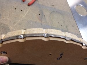
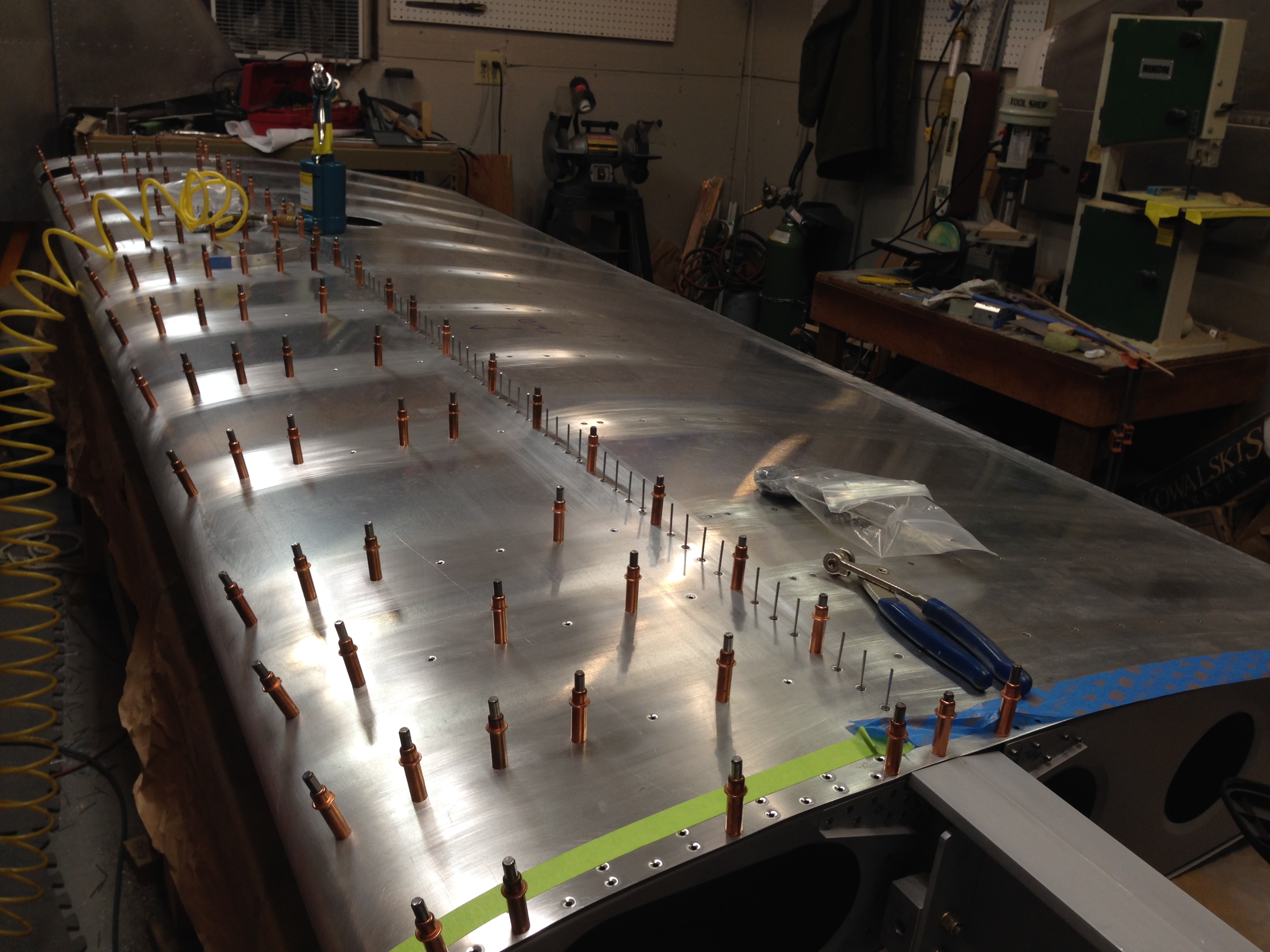
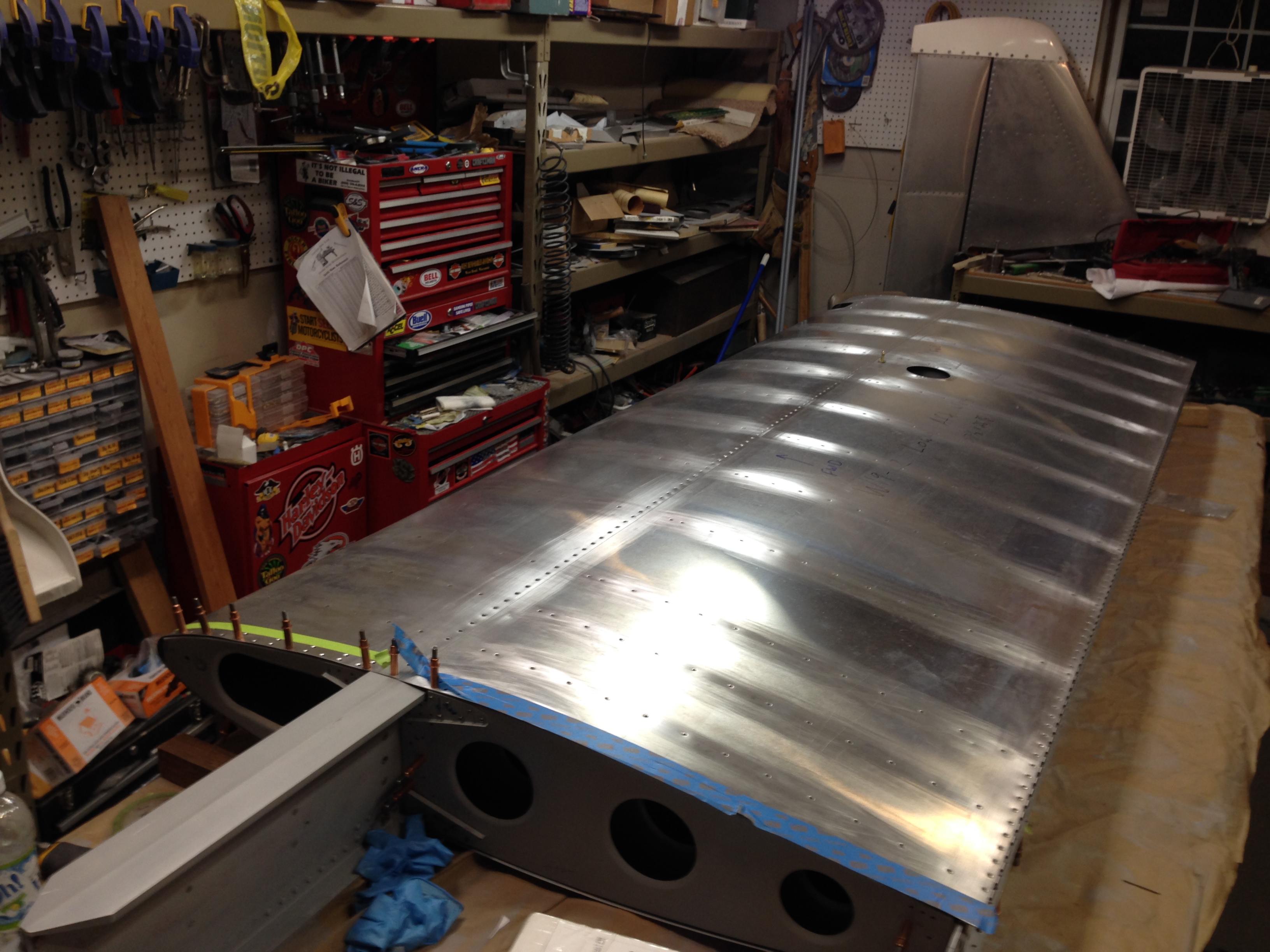
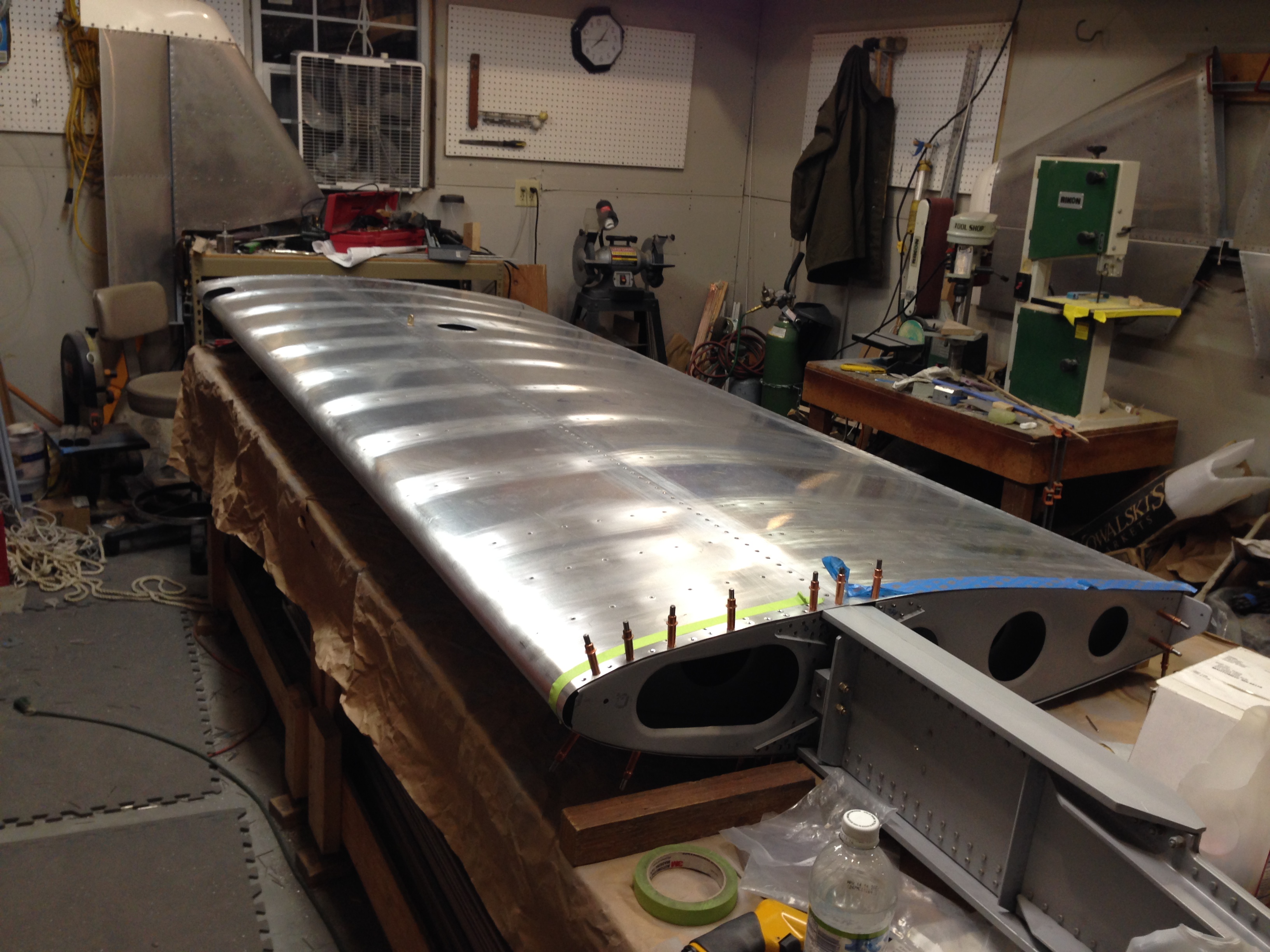
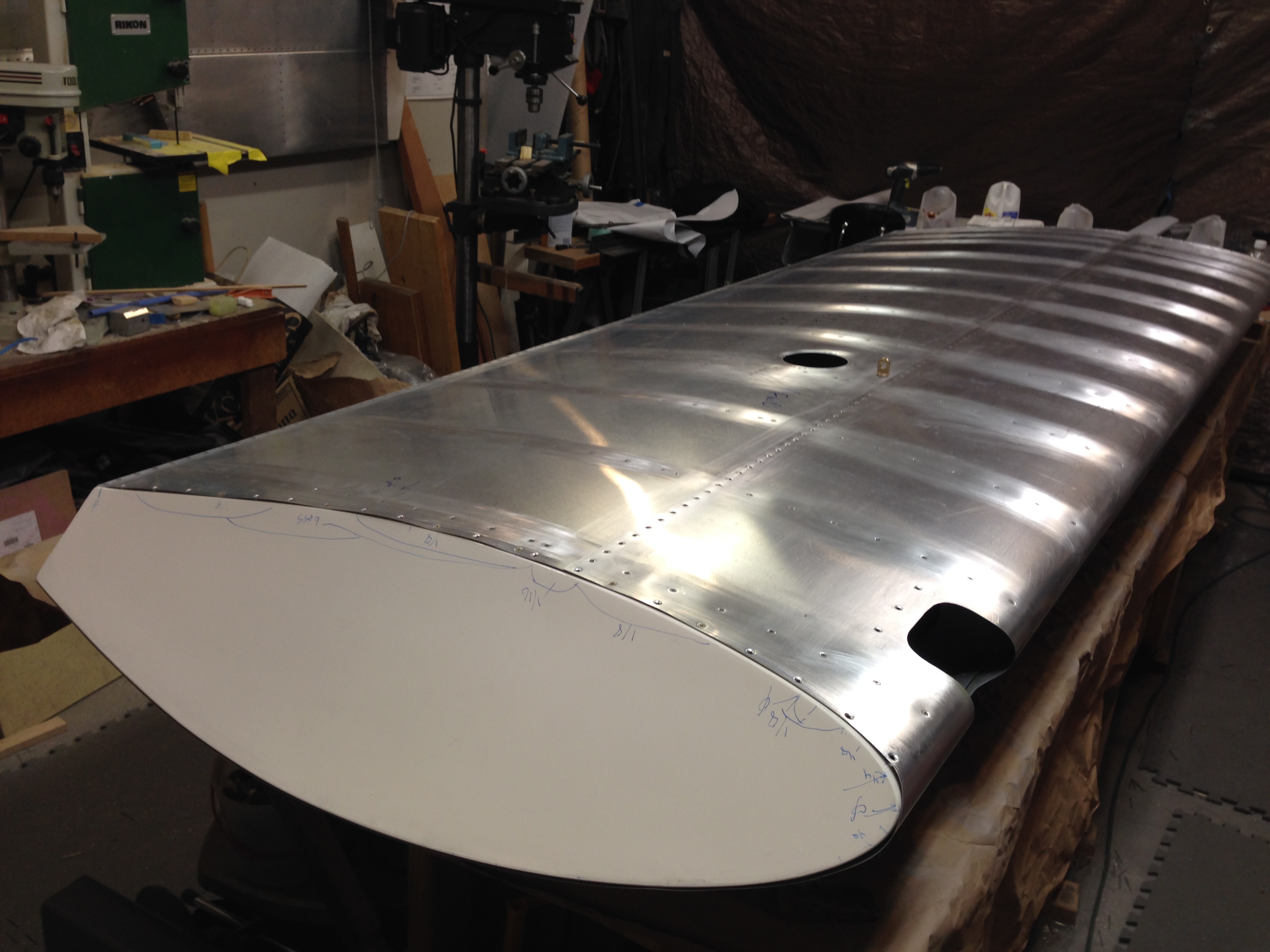
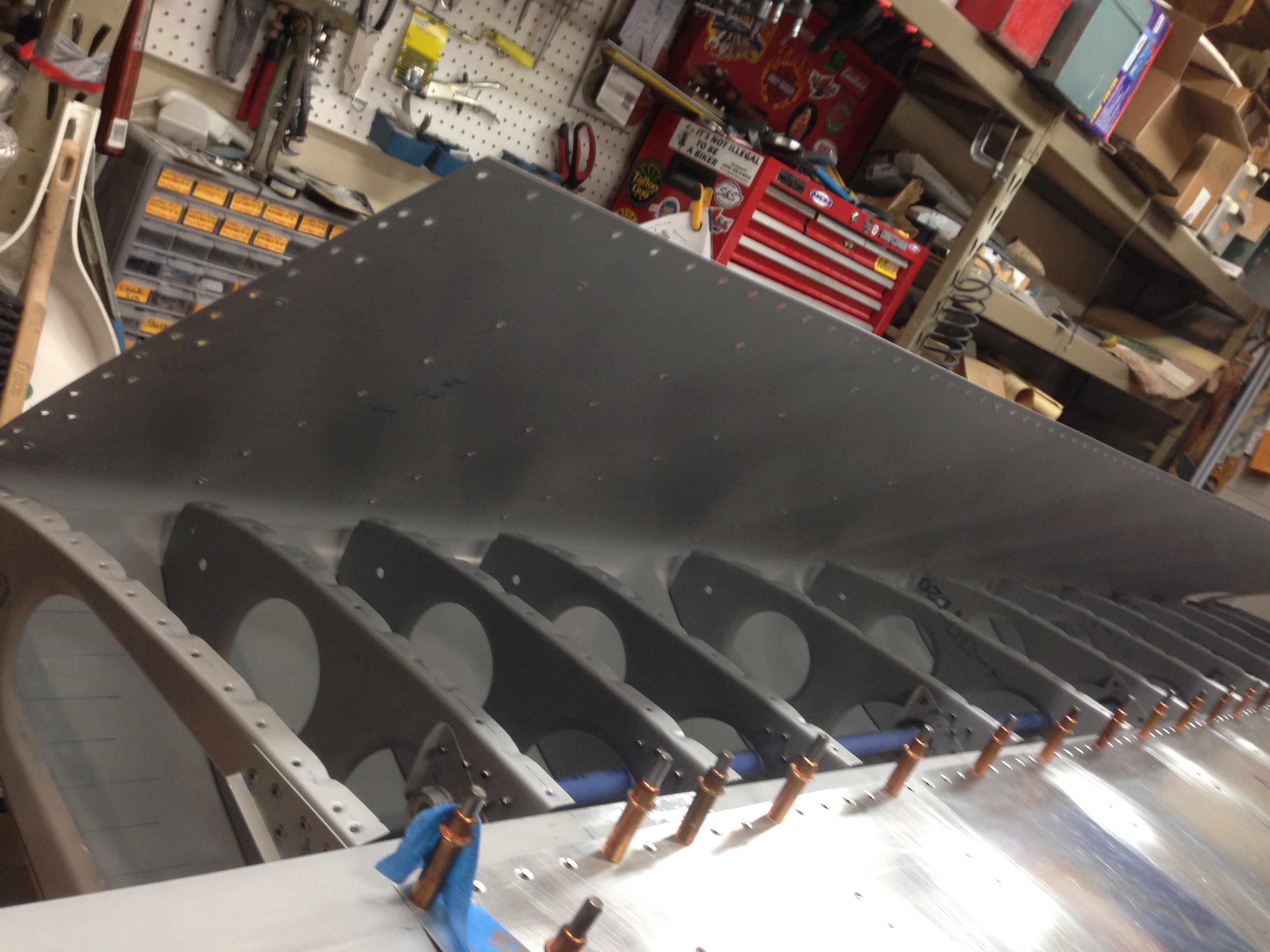
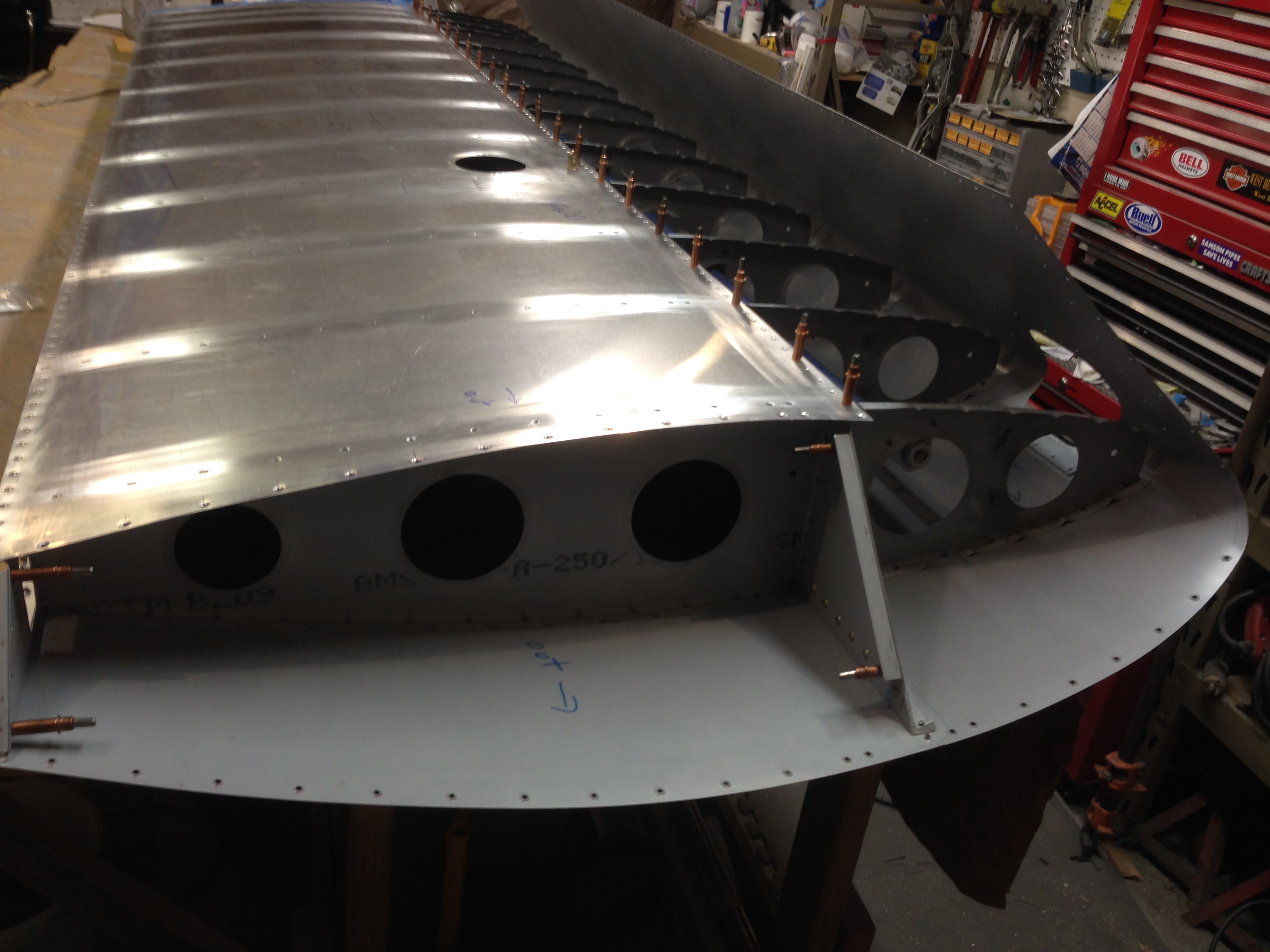
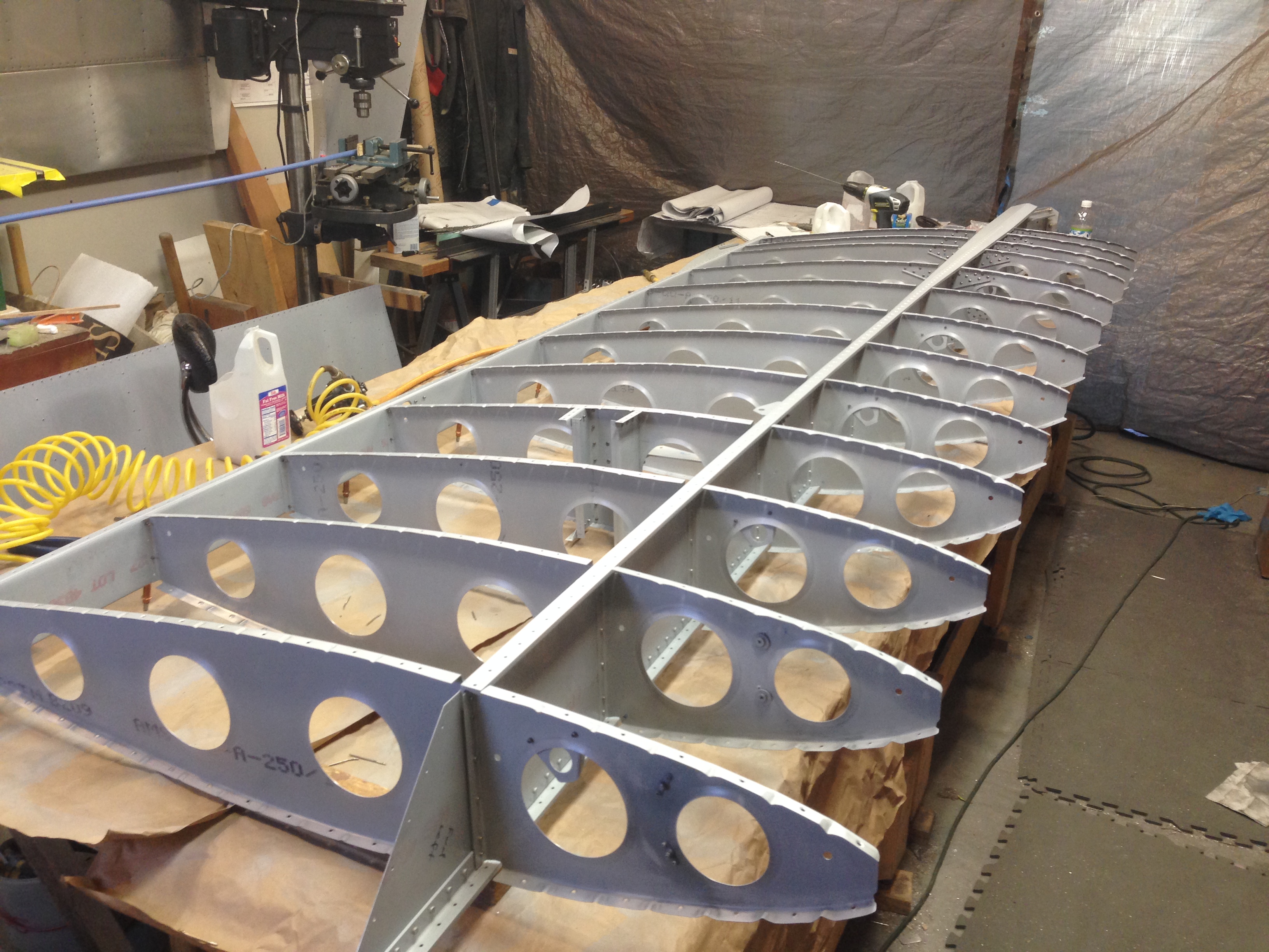
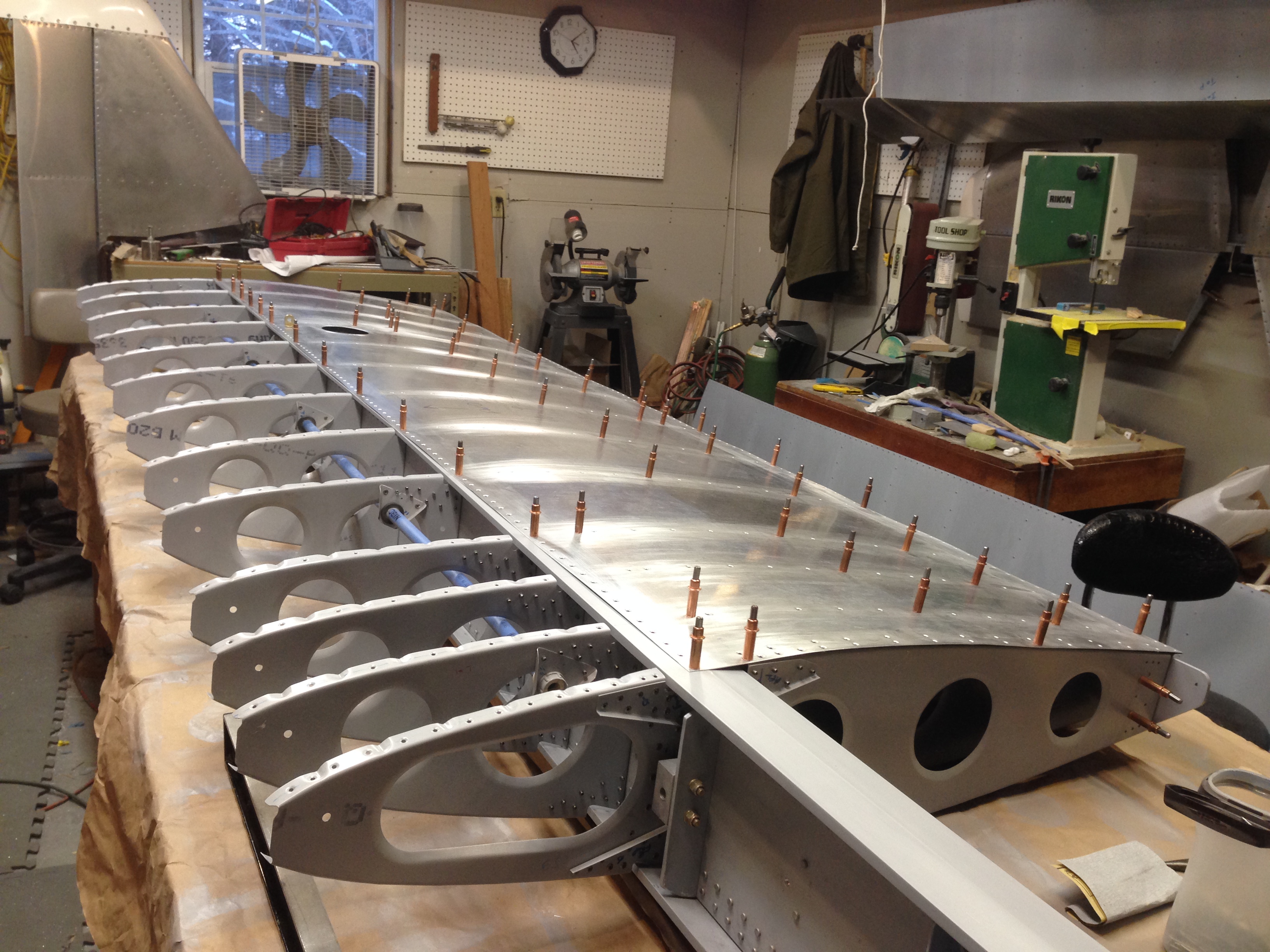
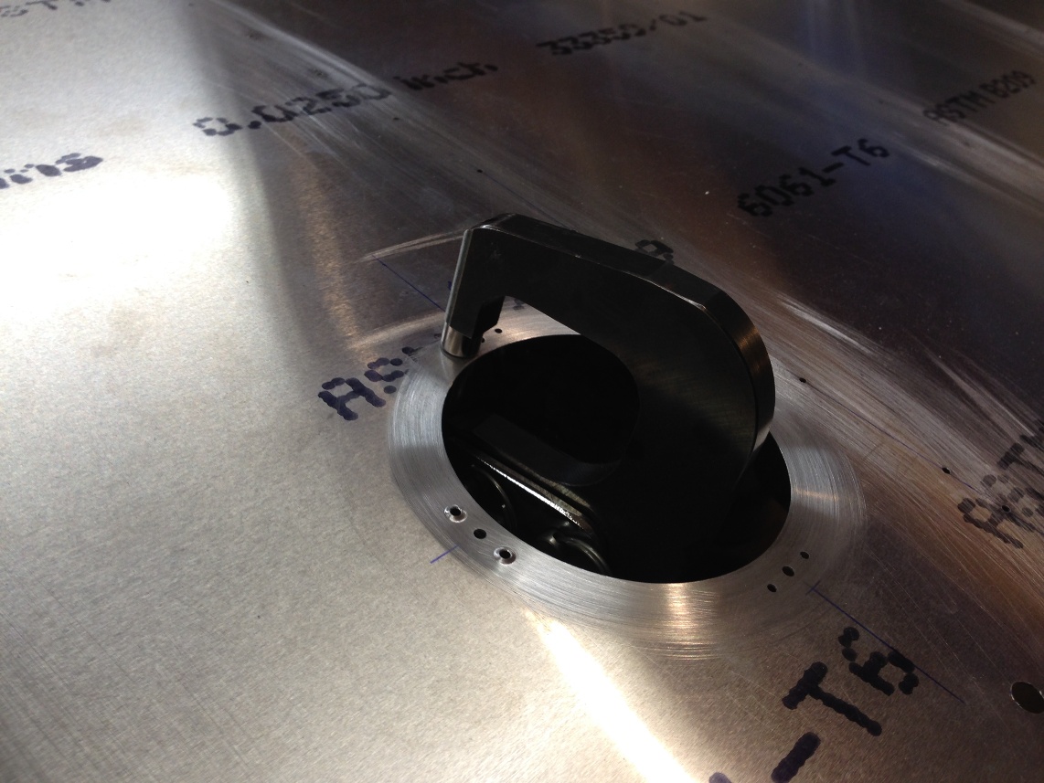
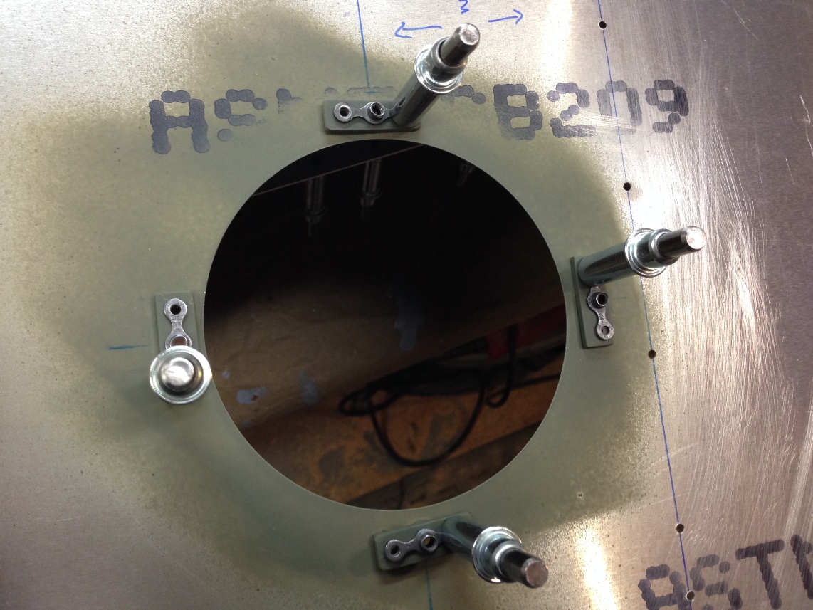
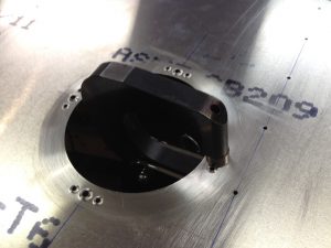
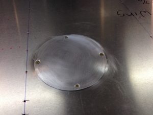
Yesterday, despite numerous interruptions with honey do list things, I was able to start and finish the inspection cover and the cut out for the tie down in the lower skin. I really like the squeezer that Gary Hall loaned us.  It is really the ticket for installing nut plates.  Tim and I decided to  use nut plates to mount the inspection covers.  While I am behind the decision it turns a 3 minute drill and screw into 3 hours when you want to have the screws countersunk (self tapping screws are what are called out on the plans).  I have a few pictures  but to make sense of what is going on I should explain that buying countersunk nut plates would be faster (and probably smarter) but what we had were a large collection of flat nut plates.  I don’t know the MS number for the nut plates we have but I thought it would be easy enough to just add a small piece of aluminum behind the skin to provide the depth to counter sink for flush mounting rivets and mounting screws.

The procedure is pretty straight forward but it is important to keep track of what holes should be drill first and at what diameter in order to best keep everything aligned.  The procedure I followed was this:

1) drill major inspection hole and make a cover

2) Mark the center line and cross  line for screw holes in cover and skin

3) Drill screw holes with #40 bit in cover

4) Align and match drill screw holes to align cover to skin

5) Cleco nut plate to skin and drill mounting holes with #40 bit.

6) Cleco cover to skin and updrill to #30.

7) dimple cover and skin for screw (this will likely be a #6 dimple die

8) updrill (match drill) previously dimpled holes to #21 (for ample clearance for screws)

9) dimple mounting holes on skin

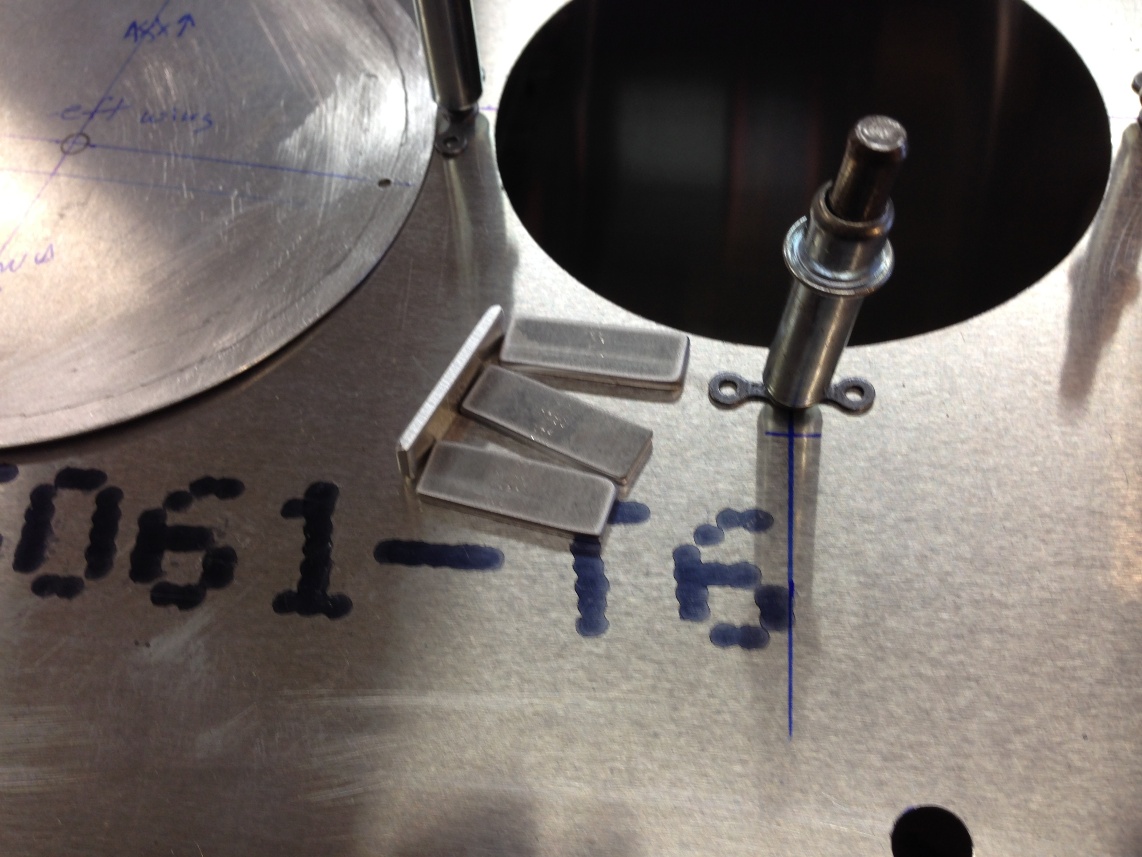
10) cut small blocks of 0.060″ to mount nut plates.

11) match drill aluminum blocks to nut plates.

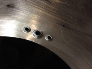
12) counter sink aluminum blocks for counter sink depths on skin for mounting rivets and screws.

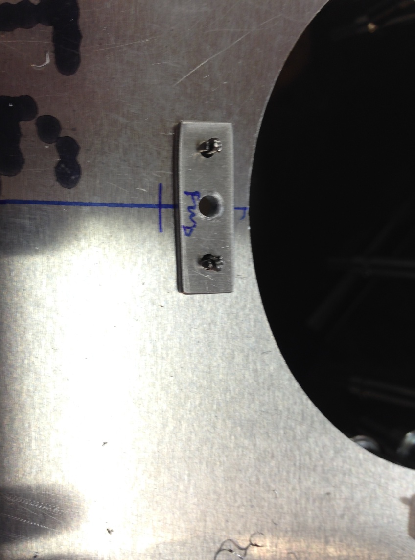
13) debur and prime mounting blocks and skin.

14) rivet aluminum and nut plates to skin (this is where the squeezer works so well.  Just by measuring the stack up of parts the rivets can be cut to length and the rivet squeezer can be set to the proper compression and it works like a champ)


Only 14 simple steps and you’re done.

Return To Left Wing Assembly