Category: Main Spar

  • Spar Rivet Replace

    Dan and I were looking over the rivets and Dan spotted a couple that were just OK.  One in particular had a little angle on it, so after a short discussion we decided to give it a couple hits from the rivet gun and bucking bar to flatten it out.  As you are probably thinking, we should have left it alone.  The bucking bar tilted in my hands and the shop head looked horrible, we were so annoyed.  One more to drill out.  This row is the -12 lengths which is the longest and you really don’t want to enlarge the hole.  Dan drilled it out really well, I’ll have to call him the surgeon.  Here is a couple pictures of the new rivet before and after.  Notice we put tape on the angles around the bucking bar to prevent scratches.

    Return to Main Spar

  • Cleaning LH Spar Parts For Priming

    Dan & I took apart the left hand spar and prepped the parts from priming.  Our method starts with deburring, then 3M (of course) 120 grit aluminum oxide sand paper, then 240 grit and a final pass with red Scotchbrite hand pads.  It is amazing how many little scratches happen when you handle these parts so much.  The long web parts took a while.  The spar caps needed a lot of work with all the drilled holes for the webs.  I was using the sand paper and it went pretty slow to get the dings out.  Later on Dan tried light pases with the vixen file and it worked great, still needs to be cleaned up with the sandpaper but really fast.  Oh by the way we use gloves when we sand because the  aluminum dust will make you hands really dirty.

    100_5764

    100_5763


    Return To Wings

  • RH Spar Riveting

    Here are some pictures of riveting the right hand spar.  The first picture is using a tungsten bucking bar we borrowed from a friend.  It weighs a lot since the density is so awesome.

    IMG_2198

    This next photo shows a really difficult area to buck the rivets.  Not even the little tungsten bar would fit between the angles.  We fabricated this bucking bar from a piece of round stock and a bolt.  Notice we had to machine one side of the bolt, we also rounded the edge so it would fit in the radius of the spar angle.  These rivets are pretty long so they take a little more from the gun to set.  (We had a fun discussion about the physics of why they took more to set than the others.)

    IMG_2199

    Below is the completed row, they came out pretty well.  I would like to know how people rivet this row when they use the Sonex hammer and bolt head process.  I imagine they back rivet and machine a bolt like we did.

    IMG_2200

    In the next picture the rivets are on the top row were -12’s and were a hair too long by the rivet gage.  We borrowed this gauge from a friend and it is really nice to check the rivet length before and the shop head diameter and height once set.

    IMG_2201

    Well we tried the -12 and a couple were OK but then they started to dump, or mush to one side.  We think I was tilting the bucking bar up a little and the long rivet would mush over from that misalignment.  We drilled those out, which is a pain since they are so long.  We shortened the rivets to match the gage length.  We used a belt sander but they got hot quickly.  I didn’t want to over heat them  in case that would change their properties.  I’ve heard about rivet cutters, but pretty expensive for a handful of rivets.    In the end we got them all done.

    IMG_2202

    Return to Wings – Main Spar

  • Main Spar (right)

    So many small details that we have documented with photos and emails back and forth but so few posts on the web site.  We need a secretary….

    In November of 2012 the right wing box was assembled for the first time and in December and January (2013) the ribs were match drilled to the spar, up drilled and the gussets were attached.  Many web sites (Blogs) keep track of hours meticulously but we are really bad at it.  I (Dan) try to spend some time each available day in but there are many days that do not allow any time to work on the plane.

    Regardless, in late January everything was in place to begin assembling the right spar.  Counter sinking was done, dimpling was done as well as de-burring and light priming.

    On Monday night I drove the first few (flush) rivets on the right spar.  They turned out pretty good but we are using conventional riveting with a pneumatic rivet gun (3x borrowed from Gary Hall, our Harmen Rocket builder friend) and bucking bars.  We found the quality of the flush rivets was very good when using the conventional method with the proper counter sink depth.  I wrote up a little analytical evaluation of the countersink calculation that seemed to be pretty reliable.  The bottom line is that for a 110 degree countersink and 0.032″ skin, an AN426-AD-5x rivet required a minimum of 0.022″ more diameter countersink than the rivet head width at it’s widest.  I will have to post the calculations but the rivet head is 0.275″ wide so the counter sink needs to be in the order of 0.300″ diameter.

    Counter sink diameter

    After driving a small number of rivets it became apparent that this job would be much easier with two.  So the following night, Tim and I got together and started driving rivets.  As was expected, we got progressively better at it as each rivet was driven.  That was until we go to the section of flush rivets on the spar where the rivets are buried between the upper spar cap and an angle brace.  Our best efforts resulted in driving a couple less than ideal rivets and drilling out most that we put in due to them being dumped on the shop side.  We debated back riveting (putting the flush head against a smooth metal surface and driving the shop end with a hammer and bolt like Sonex advocates)  these are hard to get at rivets and eventally decided to sleep on the issue.

    Return To Wings  – Main Spar

  • Countersinking Spar

    Dan spent a lot of time figuring out the proper countersink depth to allow the dimple to properly form over it.  See this post  Dan used the countersinking cage and bit where we could.  We purchased it from Pan American Tools.

    01202013080

    On the spar cap the cage would not fit so we used the drill press and measured the outside diameter of the countersink to get the right size.

    01202013081

    01212013083 01212013082

    We had purchased a 5/32 dimple die for our C Frame dimpler but they did not seat as well as wanted.  In the end we aligned the sheetmetal over the countersunk layer and placed the bolt or rivet in the top flat sheetmetal hole.  We used a arbor press to compress the rivet into the countersink.  This created a really tight and crisp dimple.  It got tricky in some spots so a little collar was used.

    01272013086 01272013087 01272013088 01272013090 01272013092 01272013094 01272013099

    Here is our countersunk and dimpled spar layers:

    01292013104

    Return To Wings  – Main Spar

  • More Ribs Located on Spar

    We primed the rib gussets (and the rib corners they will cover) and riveted them to the ribs.  Man, there are a lot of holes in those gussets.  Lots of clecos on and off as you are riveting.  Some of the rivets are close to the flanges so we used collars of different heights to raise the rivet gun nose while riveting.  Of course we drop them on the floor or bench and spend 5 minutes finding them.

    Here are some more pictures of the ribs cleco-ed to the spar.  Note that the spar is not riveted yet.

    01192013079 01192013077 01192013078

    Looking Good!

    Return To Wings – Ribs

  • Updrilling RT Spar

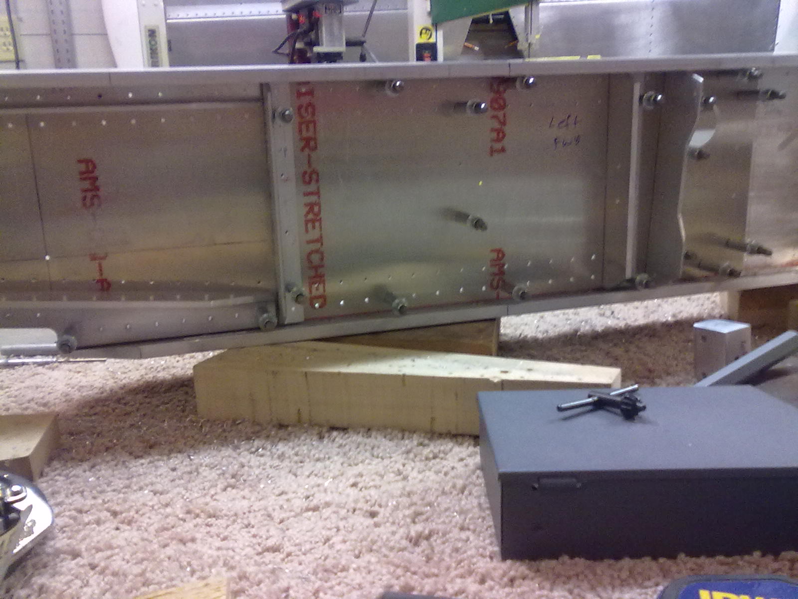
    Dan updrilled the right spar.  To do this we installed the bolts first.  We spent a lot of time getting a “tight fit” for the AN bolts as stated on the plans .  We bought a bunch of reamers to the right fit, sometimes we would need a .0005″ smaller reamer.  (I have to admit this was my, Tim’s, complusiveness but who doesn’t like a good fit.)  I will write up a summary on reamers and post it in the tools section.  The bolts really align the spar laminates and the clecos can hold it tight.  Dan decided to use the small drill press to get a perpendicular bore, he had to move it around on the workbench with the spar elevated and leveled.

    01042013057

    Notice all the 1/8″ copper clecos in the image below:

    01052013058

    01062013059

    After up-drilling notice all the 5/32″ black clecos

    01072013060

    Return To Wings – Main Spar

  • Spar Attach Block Locating And Match Drilling

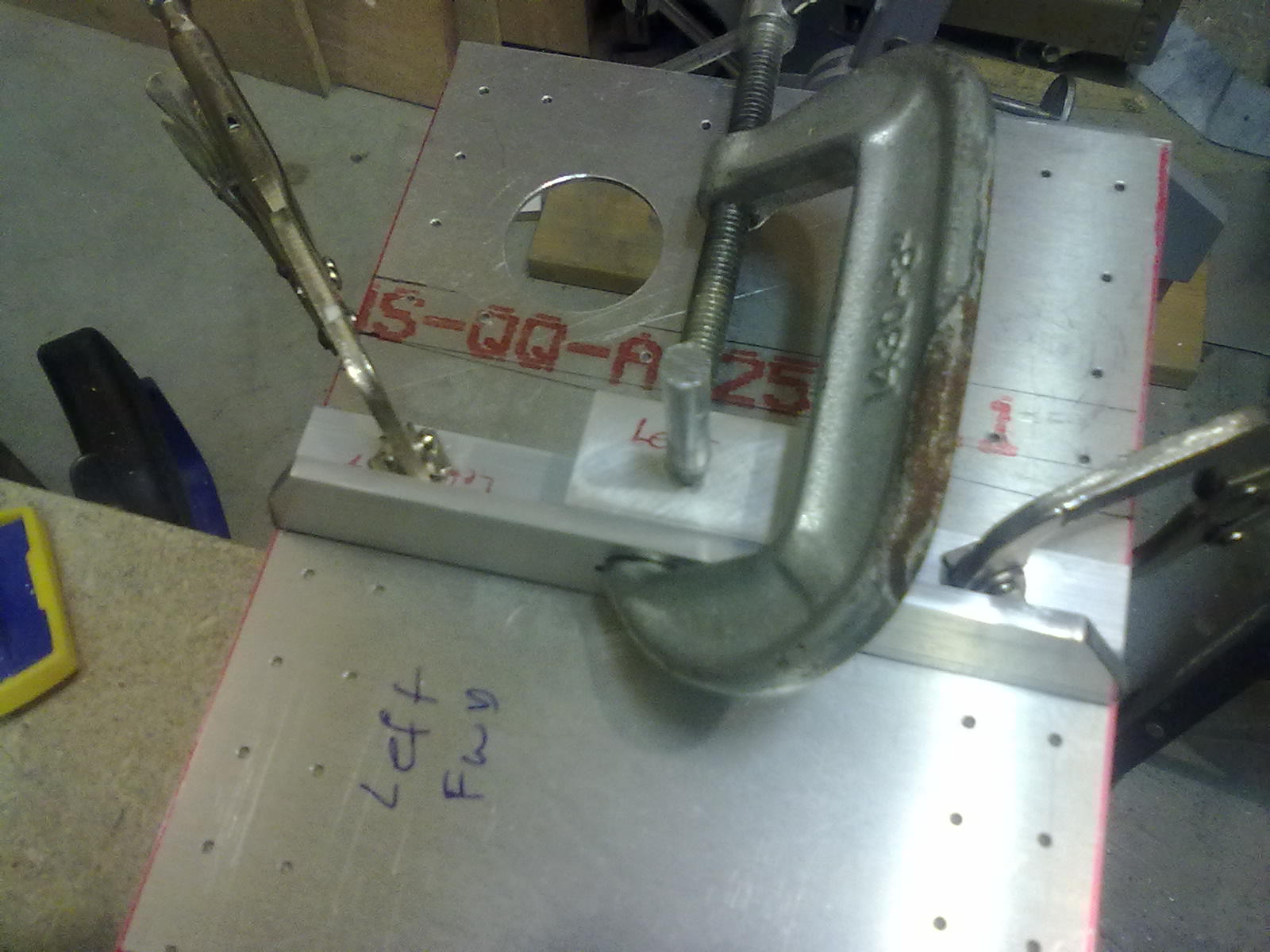
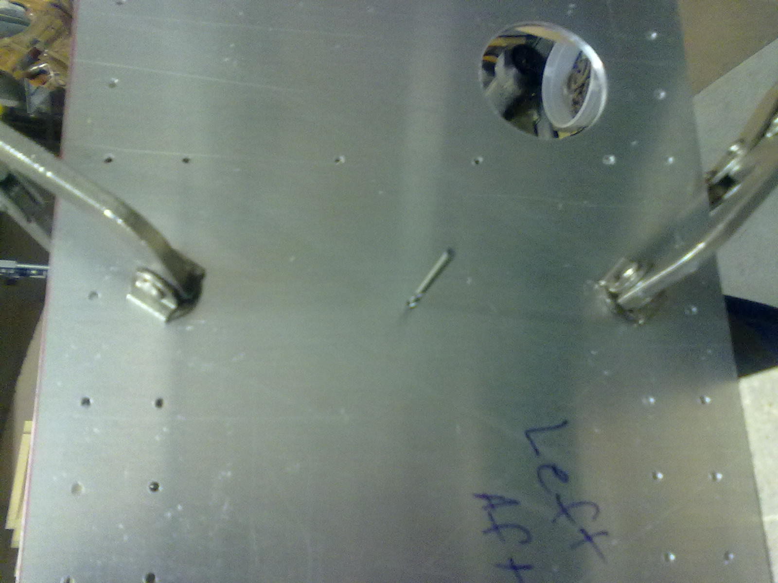
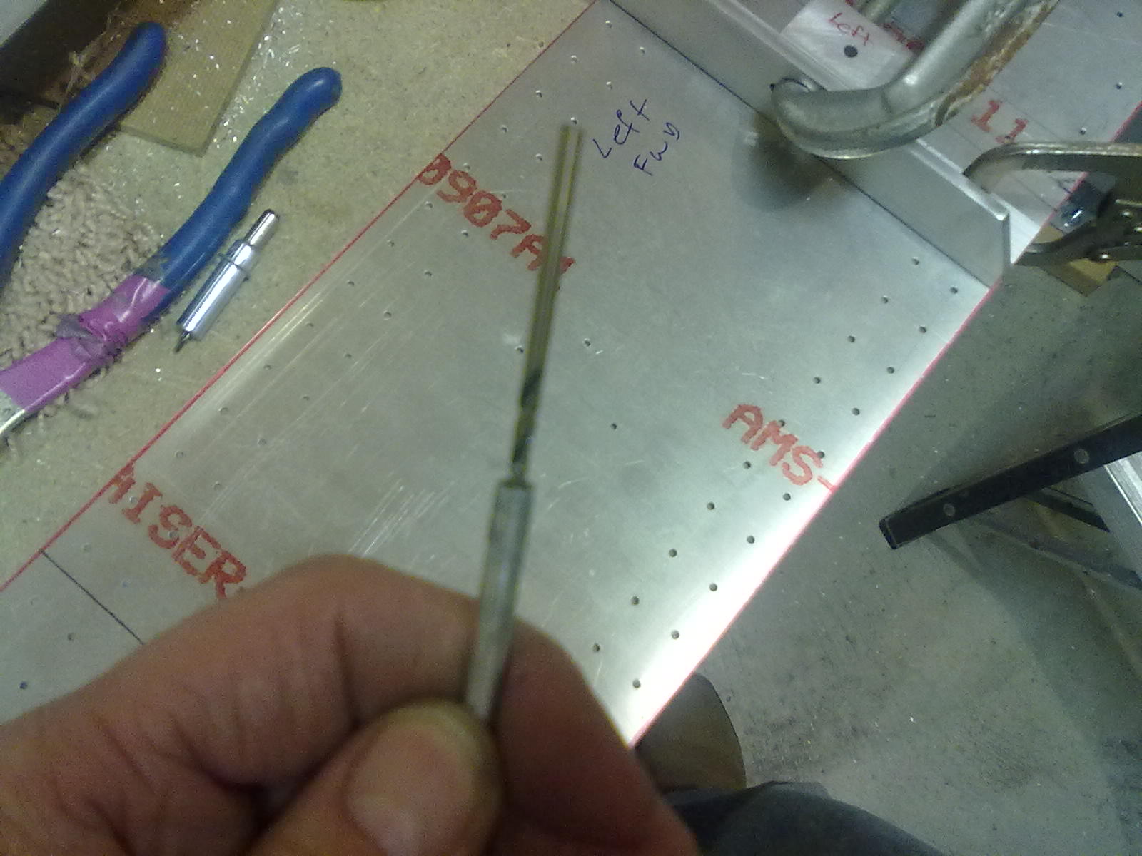
    11/4/12 – Dan got in the garage and match drilled some of the spar assembly.  To locate the spar spar attach block, Dan made a pin to fit in the 3/16 hole in the attach block.  He also made a #40 hole in one end this pin.  With a #40 drill bit in this end we can locate the attack block to the correct hole in the spar web.

    Return To Wings – Main Spar

  • Spar LH Caps

    (Been a while since I have been at the workshop since learning and replacing a retaining wall in the spring/summer 2012 – Tim)

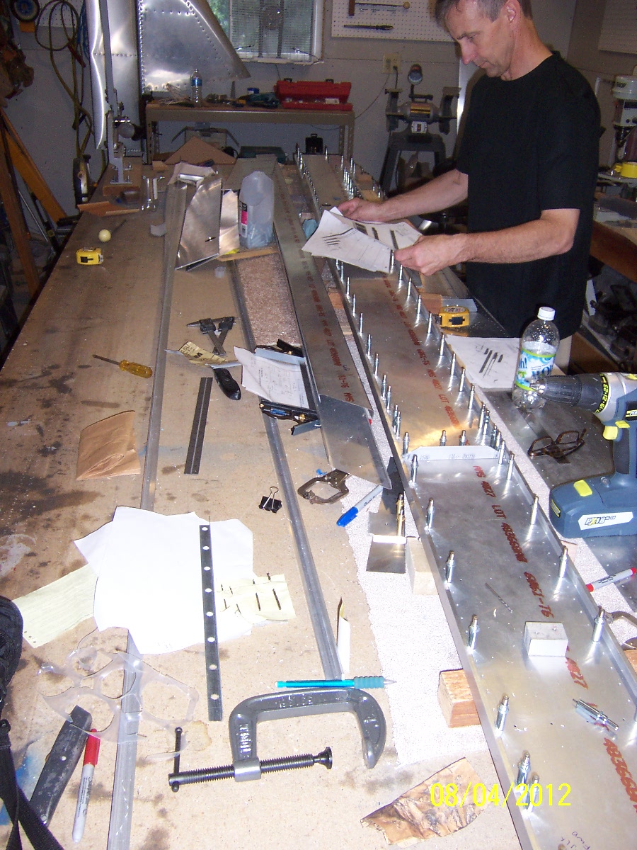
    Having matched drilled  and clecoed most of the RH (Right Hand) spar we began work on the LH spar.

    First order of business is laying out the correct order of all the spar layers.  The plans are a little tricky with the right & left sides so Sonex provides some 3D CAD exploded views (RH & LH) .  These still take a little head scratching since one does not want to mess up the expensive spar caps.

    Dan came up with a good way to set the spar cap distance.  He placed two carpenter squares, face to face, on one ruler so we could set the outside spar cap distance.
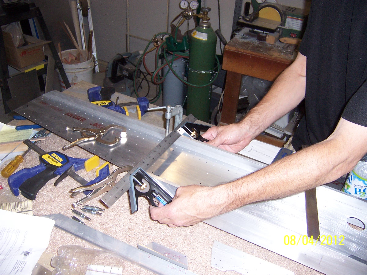
     Sonex sells (or we could make) precision spacers that fit between the spar caps, but we would be depending on the precision of the spar cap “T” leg dimension.  Another side note is that the match drill holes are in the spar web, so they need to be on top.  This makes the spar caps’ “T” leg on the bottom underneath the spar web .

    Our method measures the outside distance which is the dimension shown in the plans.  We double-check setting the gap between the squares with a precision ruler and with a 8″ digital mircrometer that I borrowed from work.  Since we are measuring an outside distance there is some feel to it.  There is some friction, or tightness, of our outside gauge against the spar caps.  We tried to be consistent with the same amount of drag feel of the gauge.  You can easily have the gauge not perpendicular to the caps.  To help this we would put pen marks on the caps with a square so we could line the gage up with them.
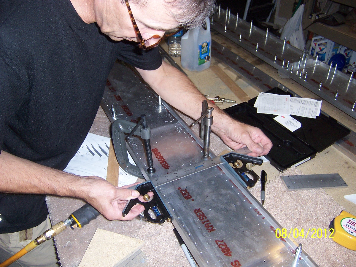
    We would clamp the spar caps on the spar web and check the distance with the gage.  The next step is to make sure the spar web is centered with respect to both caps.  This took some iterations, but it got easier with two people.

    Once the we felt the caps were clamped in the right place we drilled and clecoed one end , then the the end, then the middle.  We kept splitting the distance to be in the middle of the gap.  After about six times of this we just match drilled the rest.

    To get a good perpendicular drilled hole we place a block of aluminum on the spar web next to the drill bit.  By using the two edges of the corner it helps us see if the bit is off in either angle.

    Return To Wings – Main Spar

  • RH Spar Layout and Match Drilled

    Summer Months, June – July      (More Info & Pictures Coming)

    Dan got the all layers together for right hand spar and match drilled them.  Quite a bit of work and a little imtimidating to drill that first hole with the $$ spar caps and all the time put into the spar webs.  Great job.

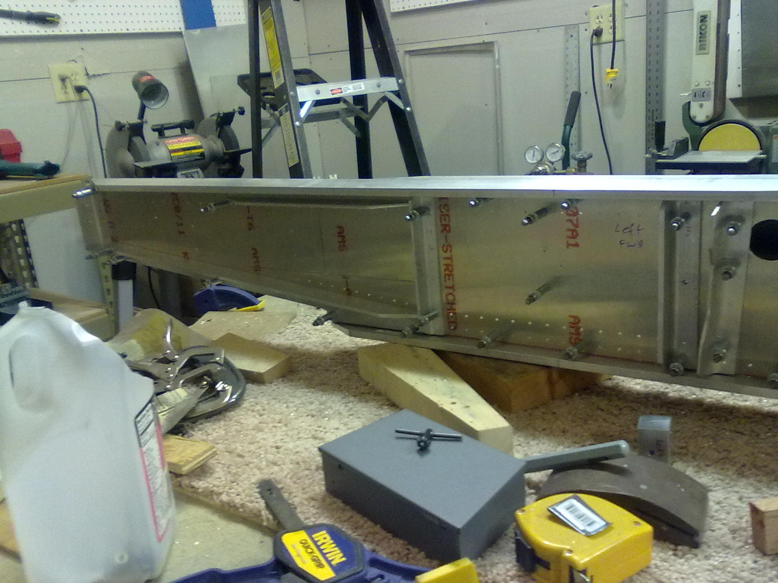
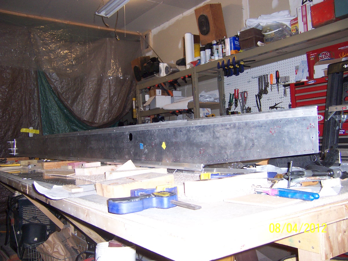
    We have the assembly cleco-ed together.  A couple of the angle parts still need to be added.

    (These pictures were taken recently)

    Return to Wings – Main Spar

Back