Finish Riveting Left Hand Spar

Dan & I worked on the inboard rivets.  In this area the spar caps are the widest so one needs to pay more attention to the rivet gun and bucking bar.  This is also where the flush rivets are.  In addition there are angles on the spar web that make it thicker.  This means longer rivets and for some reason they are harder to set perfectly, especially the long flush ones.  Here is our progress for the day:

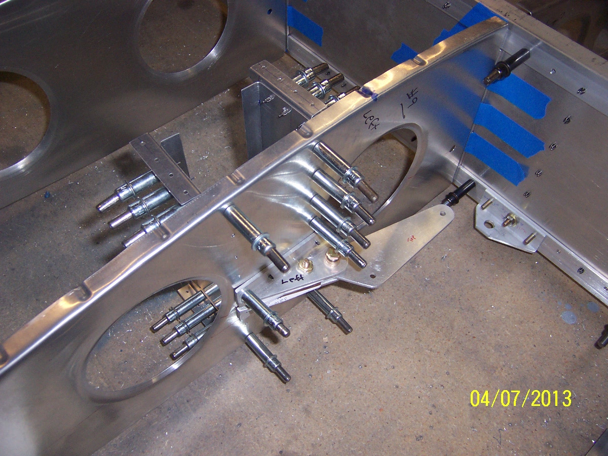
Dan is really good using the rivet gun with the flush set.  But I had “issues” with the bucking bar on these rivets in the top row of the picture. (by the way the spar is mounted upside down).

The plans call out for -12 lengths but our rivet gauge shows they were a tad too long.  We had trouble on the Right Spar in this spot but we thought we had more experience now so we tried it.  The first was OK but the second and third collapsed to one side, its like they form the head offset from the main stem.  These were a pain to drill out due to their length.  We decided to heed the rivet gauge and sand down the rivets a 1/16 or so so they fit the gauge.  I still had trouble and a few collapsed off-center.  What a pain.  Dan was not having fun drilling these out.  It was a long frustrating session.  I was probably tilting the bucking bar as it collapsed but the process happens so fast I am not sure what happens.   In the photo below you can see a row of holes that you need a special bucking bar to access  due to distance between the angle and the spar cap (see this post):

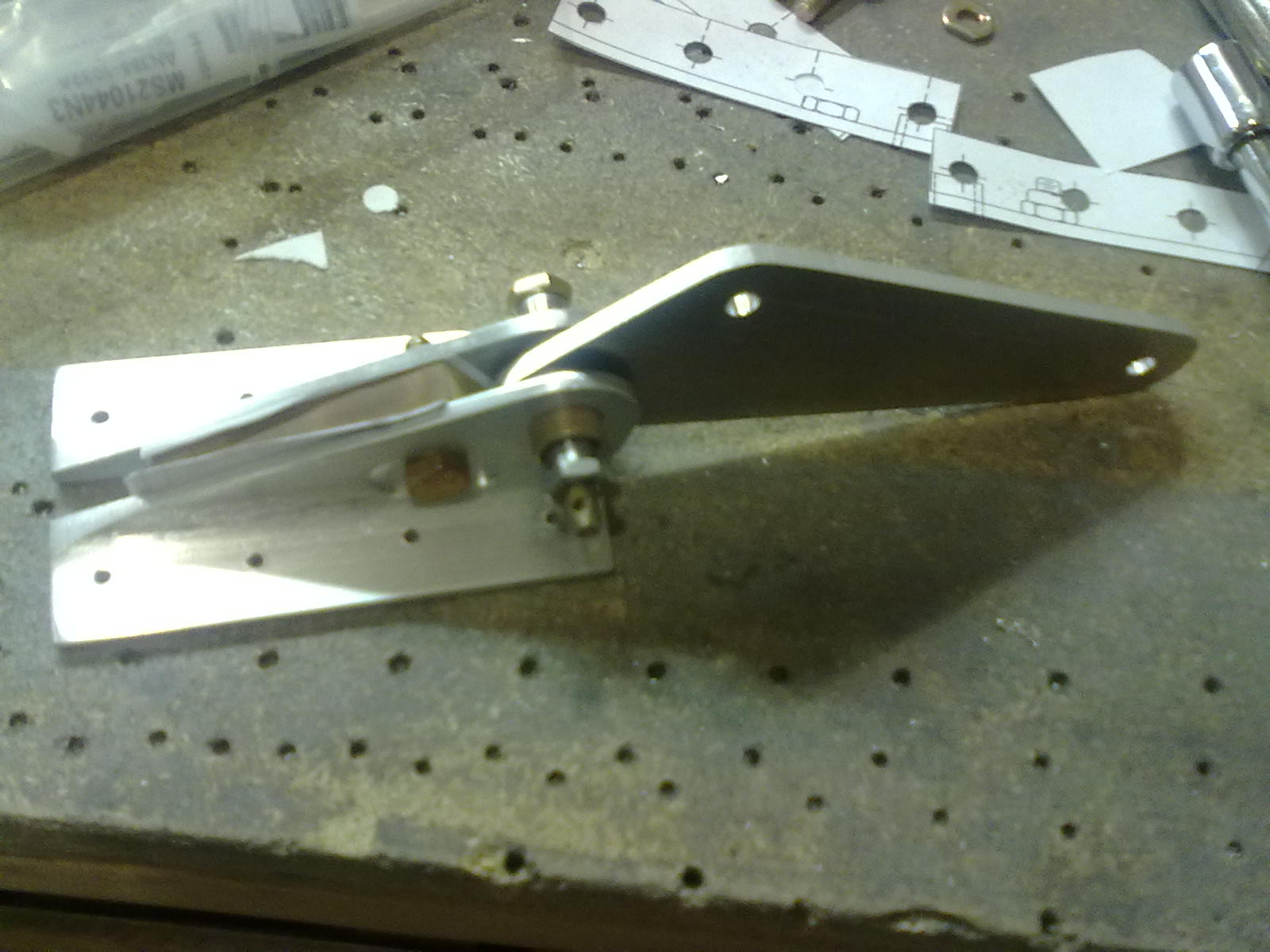
Our tool from the Right Hand Spar did not fit, so after I left, Dan ground a new bolt to fit there.  Dan talked his wife into bucking those really hard to reach rivets.  Thank You Thank You.  Those are hard to do since you cannot see the rivet so its hard to tell of you are the right angle.  They got them all done, awesome.

Return to Main Spar

Priming Assembly Start Riveting Left Hand Spar

During the week Dan finished up the spar cap preparation.  Dan mixed up some Har-Hyde self etching primer and sprayed the left spar parts.  I arrived just as they were finished drying, what great timing.  Dan put a really nice thin coat on, notice how you can still read the red printing on the parts.

We assembled the left spar by first putting in the AN bolts and screws.  Due to our “bolt-fit-obsession” you cannot cleco the parts first and expect the multiple bolts to go through all the layers in the assembly.

Bolts & Screws In Spar First


Added some black clecos and ready to rivet.

We borrowed a 3X rivet gun from a friend who is building a Rocket.  Our EAA Tech Counselor suggest to start in the middle and work out to both sides.

We got about 5 rib bay sections done when I had to leave.  Dan was able to finish most of the dome head rivets to the tip.  Here are some of the rivets:

Return to Main Spar

Cleaning LH Spar Parts For Priming

Dan & I took apart the left hand spar and prepped the parts from priming.  Our method starts with deburring, then 3M (of course) 120 grit aluminum oxide sand paper, then 240 grit and a final pass with red Scotchbrite hand pads.  It is amazing how many little scratches happen when you handle these parts so much.  The long web parts took a while.  The spar caps needed a lot of work with all the drilled holes for the webs.  I was using the sand paper and it went pretty slow to get the dings out.  Later on Dan tried light pases with the vixen file and it worked great, still needs to be cleaned up with the sandpaper but really fast.  Oh by the way we use gloves when we sand because the  aluminum dust will make you hands really dirty.

100_5764

100_5763


Return To Wings

Aileron Bell Crank Rib Brackets

We mounted the two vertical C shaped channels behind the aileron bell crank assembly.  There are little right angle peices that connect these channels to the skin.  All this extra structure is to stiffen the rib where the bell crank is.  The plans show to make the top face of the angle peices flush with the curvature of the rib flange, since both are riveted tot eh skin.  This took me more time than I thought it might because the rib flanges are not perfectly square, some are a little over bent, so it is hard to tell where to mount this angle bracket vertically.  Dan had a good solution to clamp a long piece of aluminum angle extrusion to several ribs on  either side of the bell crank rib.  The angle extrusion is stiff enough that it won’t bend so it will lay like the final skin on the ribs.  With the extrusion on the ribs, I could see the gap of the over bent rib flange, and mate the angle bracket to the under side of the extursion.  We think when the skin is riveted on it will pull the rib flange up a little.  Once we had the top ones done we moved the extrusion to the bottom as can be seen here :

Locating Bottom Skin Bracket For Aileron Bell Crank

Celco-ed Bell Crank Brackets:

100_5760

Top Skin Brakets Mounted

We took the wing structure apart do deburr the parts for priming.

Ready For Deburr-ing

Return To Ailerons – Wings

Aileron Bell Crank Assembly

Dan assembled the aileron bell cranks.  The bushing holes in the angle brackets were matched drilled, in the drill press, a little under and reamed to final size.  In case you don’t know bronze bushing are designed to be press fit onto bores but this casues the inner diameter to collapses a tiny bit.  We could just start the bronze bushing in by hand until it stopped.  We then checked the fit of the rotating steel bushing.  Dan polished the outside of teh steel bushing on the Scotchbrite wheel.  We thought it was good so used the arbor press to insert the bronze bushings.  There is a peice of phenolic to space the angle brackets.  We had to use a shim of paper on either side of the phenolic to get the rught feel.  (I would really prefer ball bearings  but given the limited motion of the bell branks this seems like a good design, but we both wanted a good smooth feel the rotation.)

For some reason our aluminum angle has a big inside radius so the head of the angle clamp bolt and the nut did not sit flat.  We machine a little spot face so they sit properly.  We will sand this area really smooth.

03282013161

Return To Wings – Ailerons

Aileron Bell Crank Parts

We have been working on the Aileron Bell Crank parts.  Used the scan/print spray glue method for the parts that had make to print size on them.  After the root rib trim episode we looked at the how these parts are assembled.  For example the U channel parts are stiffeners on the rib behind the bell crank assembly.  The length should be accurate but it is position so there is clearance between the end and the skins.  So there is no need to be right on the 1/64 dimension, which might save a little time for making four parts.

Aileron Bell Crank Parts

Return To Wings – Ailerons

New Aft Root Ribs

Dan cranked out two new aft ribs and since we knew they we for the root positions he did not have to make the front and back flanges.  He trimmed them a little longer so we would have plenty of edge distance from the first row of rivets:

03232013152

03232013151

Positioning the root ribs with the others:

03242013157

Put the aft wing skin on to see how it fit, Looking Good

03242013158

Return To Wings – Ribs

Too Short Aft Root Ribs

After we trimmed the aft root ribs per the dimensions on the plans and got them positioned with clamps it looked really good.  (We were working on the left wing aft root rib.)  When Dan match drilled through the bracket to the rib the hole at the edge of the rib the hole was really close to the edge, a little too close.  Really fustrating.  All the dimensions seemed right on.  We think that perhaps the holes in the bracket were a 1/32″ off and the rib position was a 1/32″ off and the tilt of the root rib doesn’t help either.  Perhaps all these little dimensions add up to the hole being off.  Dan claculated the theoritical drawing distances and there is only an 1/8″ from the hole to the edge.  Reviewing the plans there is no reason why the rib couldn’t be a little longer on both ends to give adequate edge distance.  The rib just overlaps the attach brackets.  So we discussed a doubler but decided to remake the ribs and trim them a little longer.  One advantage of scratch building is that remaking parts is not imtimidating.

This was an interesting episode, if we had looked ahead in the plans we might have noticed the rib trim dimension was not critical and could be changed.  However it would take a lot of time to research every part dimension to see what it’s function is.

Return To Wings – Ribs

Wing Root Ribs

Dan & I worked on the wing root ribs.  These start are standard ribs but trimmed shorter so you can rivet them to some aluminum angle mounted on the spars.   We read on a few websites that on the front rib one can cut out the material between the lightening holes.  This makes reaching into the wong easier for rigging.  One can see a picture of this in the Sonex website under Support – Instruction Sheets – Wing Installation/Removal Instructions .  You can see the oval in the forward root rib.  We made the root rib gussets, they are different than the rib gussets.

03172013141 100_5752 100_5755 03172013139 03172013140

Return To Wings – Ribs