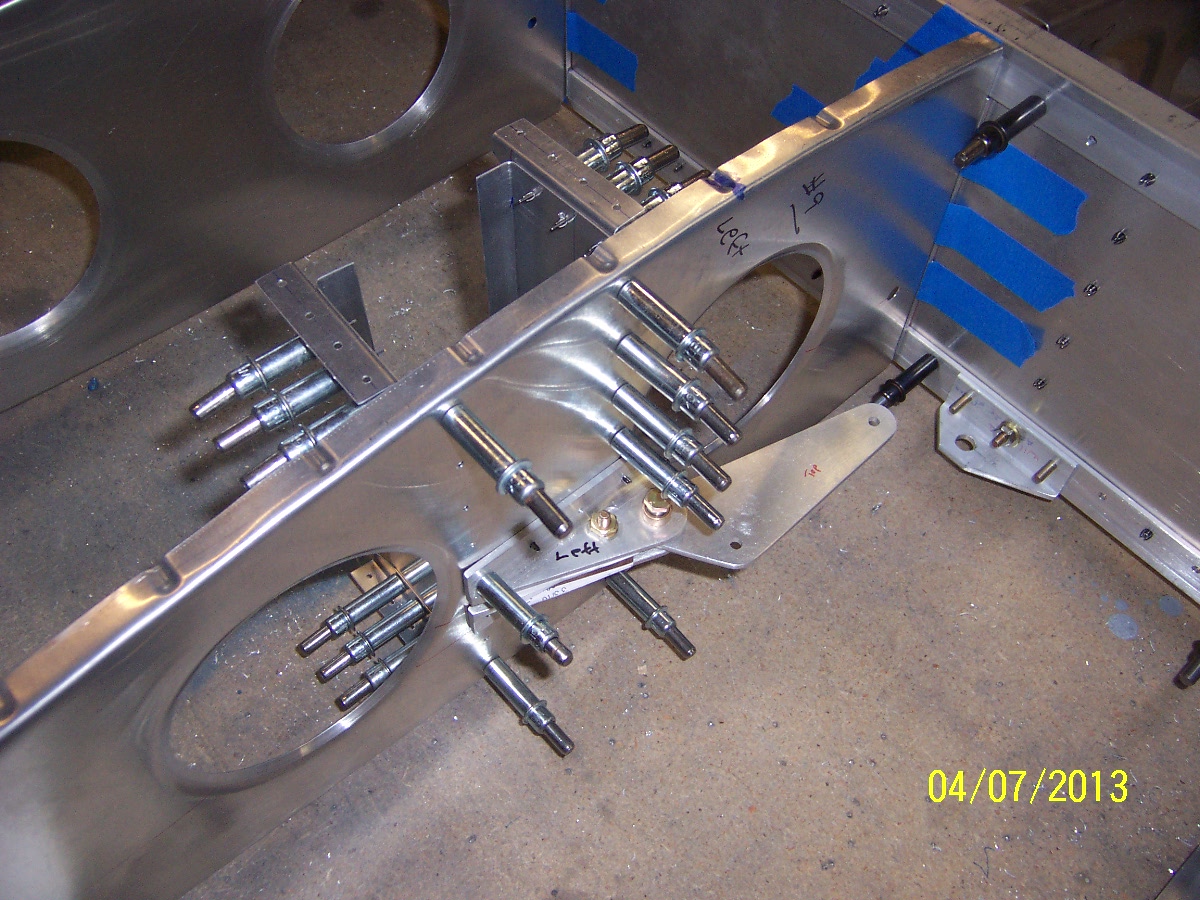
We mounted the two vertical C shaped channels behind the aileron bell crank assembly. There are little right angle peices that connect these channels to the skin. All this extra structure is to stiffen the rib where the bell crank is. The plans show to make the top face of the angle peices flush with the curvature of the rib flange, since both are riveted tot eh skin. This took me more time than I thought it might because the rib flanges are not perfectly square, some are a little over bent, so it is hard to tell where to mount this angle bracket vertically. Dan had a good solution to clamp a long piece of aluminum angle extrusion to several ribs on either side of the bell crank rib. The angle extrusion is stiff enough that it won’t bend so it will lay like the final skin on the ribs. With the extrusion on the ribs, I could see the gap of the over bent rib flange, and mate the angle bracket to the under side of the extursion. We think when the skin is riveted on it will pull the rib flange up a little. Once we had the top ones done we moved the extrusion to the bottom as can be seen here :

Celco-ed Bell Crank Brackets:

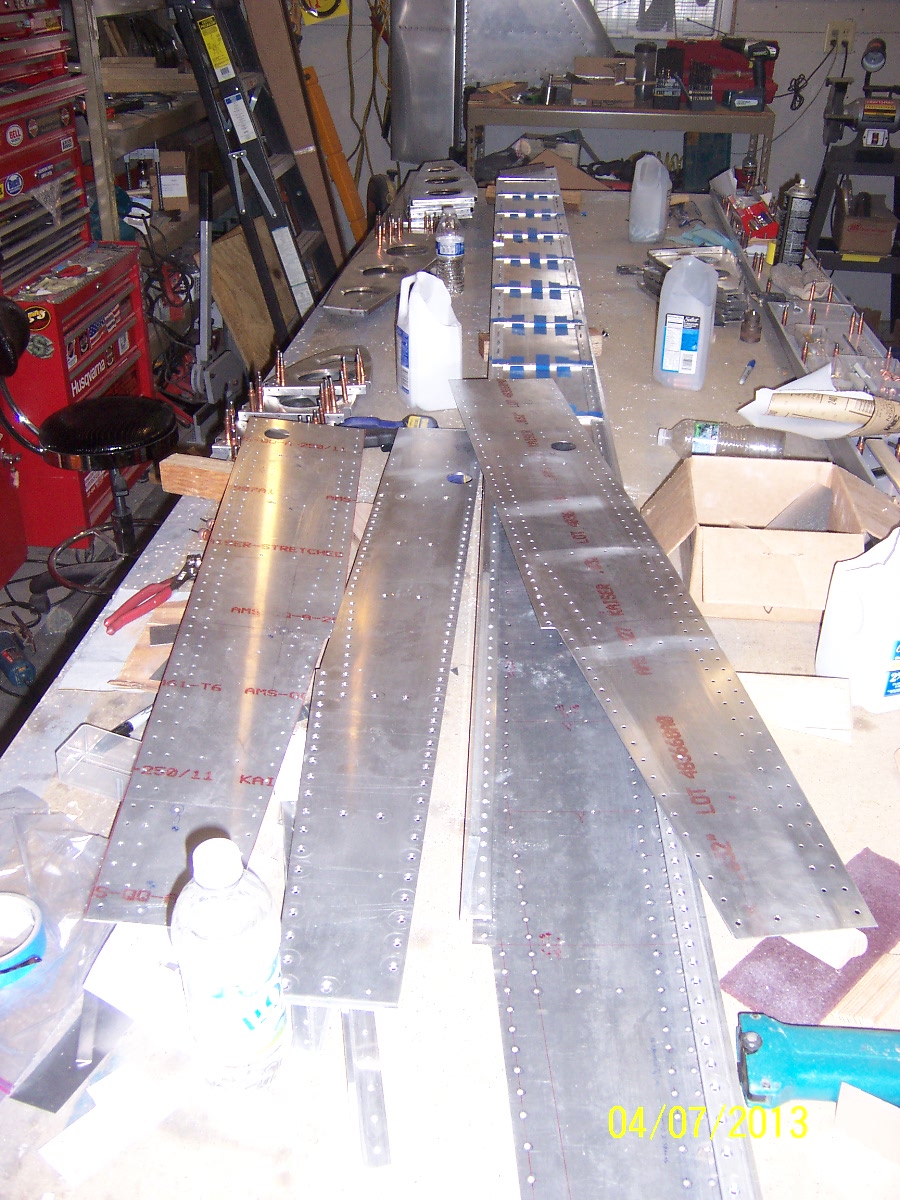
We took the wing structure apart do deburr the parts for priming.