Aileron Bell Crank Assembly

Dan assembled the aileron bell cranks.  The bushing holes in the angle brackets were matched drilled, in the drill press, a little under and reamed to final size.  In case you don’t know bronze bushing are designed to be press fit onto bores but this casues the inner diameter to collapses a tiny bit.  We could just start the bronze bushing in by hand until it stopped.  We then checked the fit of the rotating steel bushing.  Dan polished the outside of teh steel bushing on the Scotchbrite wheel.  We thought it was good so used the arbor press to insert the bronze bushings.  There is a peice of phenolic to space the angle brackets.  We had to use a shim of paper on either side of the phenolic to get the rught feel.  (I would really prefer ball bearings  but given the limited motion of the bell branks this seems like a good design, but we both wanted a good smooth feel the rotation.)

For some reason our aluminum angle has a big inside radius so the head of the angle clamp bolt and the nut did not sit flat.  We machine a little spot face so they sit properly.  We will sand this area really smooth.

03282013161

Return To Wings – Ailerons

Aileron Bell Crank Parts

We have been working on the Aileron Bell Crank parts.  Used the scan/print spray glue method for the parts that had make to print size on them.  After the root rib trim episode we looked at the how these parts are assembled.  For example the U channel parts are stiffeners on the rib behind the bell crank assembly.  The length should be accurate but it is position so there is clearance between the end and the skins.  So there is no need to be right on the 1/64 dimension, which might save a little time for making four parts.

Aileron Bell Crank Parts

Return To Wings – Ailerons

New Aft Root Ribs

Dan cranked out two new aft ribs and since we knew they we for the root positions he did not have to make the front and back flanges.  He trimmed them a little longer so we would have plenty of edge distance from the first row of rivets:

03232013152

03232013151

Positioning the root ribs with the others:

03242013157

Put the aft wing skin on to see how it fit, Looking Good

03242013158

Return To Wings – Ribs

Too Short Aft Root Ribs

After we trimmed the aft root ribs per the dimensions on the plans and got them positioned with clamps it looked really good.  (We were working on the left wing aft root rib.)  When Dan match drilled through the bracket to the rib the hole at the edge of the rib the hole was really close to the edge, a little too close.  Really fustrating.  All the dimensions seemed right on.  We think that perhaps the holes in the bracket were a 1/32″ off and the rib position was a 1/32″ off and the tilt of the root rib doesn’t help either.  Perhaps all these little dimensions add up to the hole being off.  Dan claculated the theoritical drawing distances and there is only an 1/8″ from the hole to the edge.  Reviewing the plans there is no reason why the rib couldn’t be a little longer on both ends to give adequate edge distance.  The rib just overlaps the attach brackets.  So we discussed a doubler but decided to remake the ribs and trim them a little longer.  One advantage of scratch building is that remaking parts is not imtimidating.

This was an interesting episode, if we had looked ahead in the plans we might have noticed the rib trim dimension was not critical and could be changed.  However it would take a lot of time to research every part dimension to see what it’s function is.

Return To Wings – Ribs

Wing Root Ribs

Dan & I worked on the wing root ribs.  These start are standard ribs but trimmed shorter so you can rivet them to some aluminum angle mounted on the spars.   We read on a few websites that on the front rib one can cut out the material between the lightening holes.  This makes reaching into the wong easier for rigging.  One can see a picture of this in the Sonex website under Support – Instruction Sheets – Wing Installation/Removal Instructions .  You can see the oval in the forward root rib.  We made the root rib gussets, they are different than the rib gussets.

03172013141 100_5752 100_5755 03172013139 03172013140

Return To Wings – Ribs

Left Wing Rib Gussets

Dan match drilled the gussets on the left wing ribs.  One wants to make sure the gusset flange is mated tights against the rib flange when match drilling the rivet holes with the rib.  You don’t want a gap between the gusset flnage and the rib flange when you go to rivet the assembly to the spar.

03052013129

Return To Wings – Ribs

RH Spar Riveting

Here are some pictures of riveting the right hand spar.  The first picture is using a tungsten bucking bar we borrowed from a friend.  It weighs a lot since the density is so awesome.

IMG_2198

This next photo shows a really difficult area to buck the rivets.  Not even the little tungsten bar would fit between the angles.  We fabricated this bucking bar from a piece of round stock and a bolt.  Notice we had to machine one side of the bolt, we also rounded the edge so it would fit in the radius of the spar angle.  These rivets are pretty long so they take a little more from the gun to set.  (We had a fun discussion about the physics of why they took more to set than the others.)

IMG_2199

Below is the completed row, they came out pretty well.  I would like to know how people rivet this row when they use the Sonex hammer and bolt head process.  I imagine they back rivet and machine a bolt like we did.

IMG_2200

In the next picture the rivets are on the top row were -12’s and were a hair too long by the rivet gage.  We borrowed this gauge from a friend and it is really nice to check the rivet length before and the shop head diameter and height once set.

IMG_2201

Well we tried the -12 and a couple were OK but then they started to dump, or mush to one side.  We think I was tilting the bucking bar up a little and the long rivet would mush over from that misalignment.  We drilled those out, which is a pain since they are so long.  We shortened the rivets to match the gage length.  We used a belt sander but they got hot quickly.  I didn’t want to over heat them  in case that would change their properties.  I’ve heard about rivet cutters, but pretty expensive for a handful of rivets.    In the end we got them all done.

IMG_2202

Return to Wings – Main Spar

Main Spar (right)

So many small details that we have documented with photos and emails back and forth but so few posts on the web site.  We need a secretary….

In November of 2012 the right wing box was assembled for the first time and in December and January (2013) the ribs were match drilled to the spar, up drilled and the gussets were attached.  Many web sites (Blogs) keep track of hours meticulously but we are really bad at it.  I (Dan) try to spend some time each available day in but there are many days that do not allow any time to work on the plane.

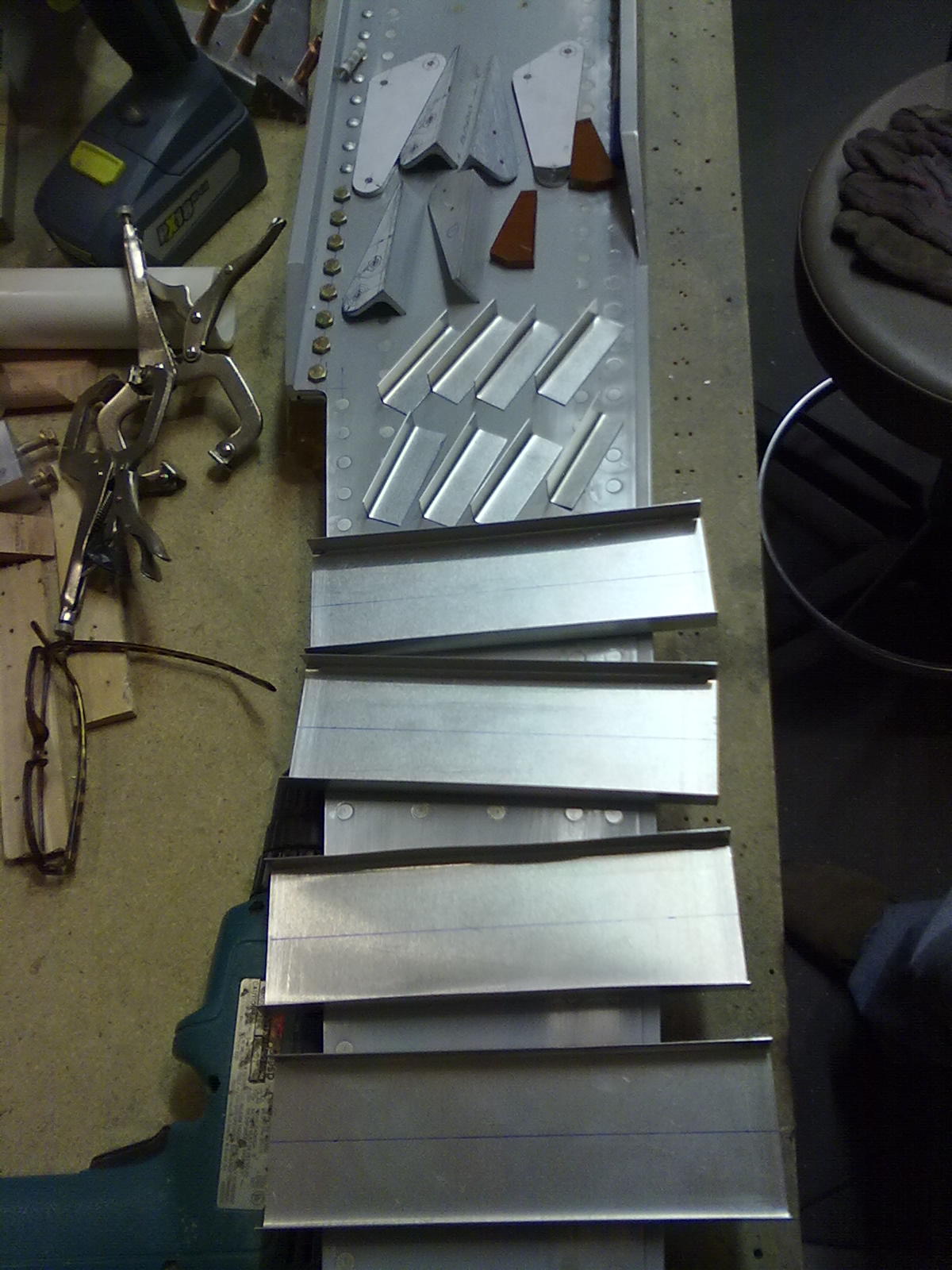
Regardless, in late January everything was in place to begin assembling the right spar.  Counter sinking was done, dimpling was done as well as de-burring and light priming.

On Monday night I drove the first few (flush) rivets on the right spar.  They turned out pretty good but we are using conventional riveting with a pneumatic rivet gun (3x borrowed from Gary Hall, our Harmen Rocket builder friend) and bucking bars.  We found the quality of the flush rivets was very good when using the conventional method with the proper counter sink depth.  I wrote up a little analytical evaluation of the countersink calculation that seemed to be pretty reliable.  The bottom line is that for a 110 degree countersink and 0.032″ skin, an AN426-AD-5x rivet required a minimum of 0.022″ more diameter countersink than the rivet head width at it’s widest.  I will have to post the calculations but the rivet head is 0.275″ wide so the counter sink needs to be in the order of 0.300″ diameter.

Counter sink diameter

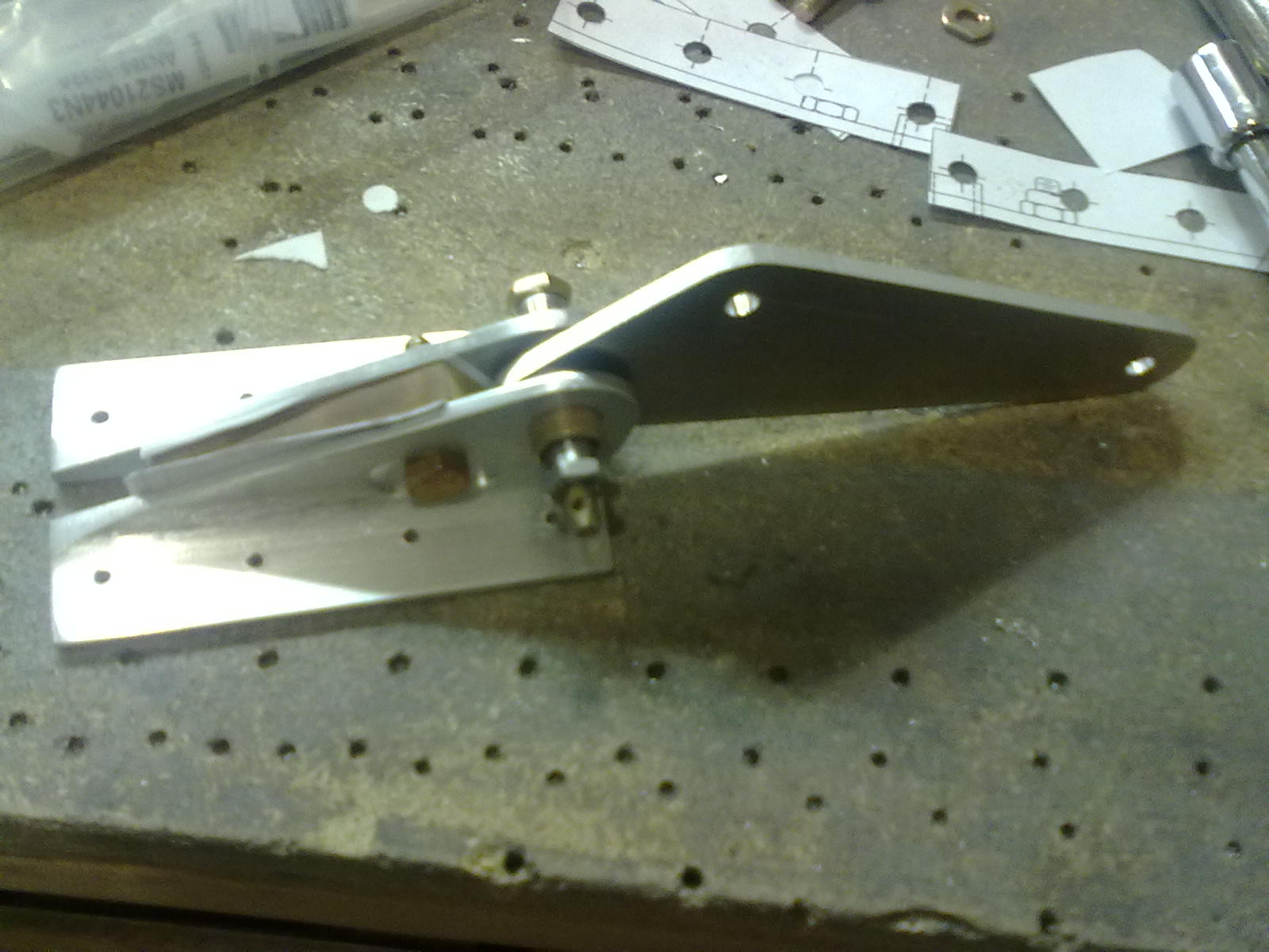
After driving a small number of rivets it became apparent that this job would be much easier with two.  So the following night, Tim and I got together and started driving rivets.  As was expected, we got progressively better at it as each rivet was driven.  That was until we go to the section of flush rivets on the spar where the rivets are buried between the upper spar cap and an angle brace.  Our best efforts resulted in driving a couple less than ideal rivets and drilling out most that we put in due to them being dumped on the shop side.  We debated back riveting (putting the flush head against a smooth metal surface and driving the shop end with a hammer and bolt like Sonex advocates)  these are hard to get at rivets and eventally decided to sleep on the issue.

Return To Wings  – Main Spar

Countersinking Spar

Dan spent a lot of time figuring out the proper countersink depth to allow the dimple to properly form over it.  See this post  Dan used the countersinking cage and bit where we could.  We purchased it from Pan American Tools.

01202013080

On the spar cap the cage would not fit so we used the drill press and measured the outside diameter of the countersink to get the right size.

01202013081

01212013083 01212013082

We had purchased a 5/32 dimple die for our C Frame dimpler but they did not seat as well as wanted.  In the end we aligned the sheetmetal over the countersunk layer and placed the bolt or rivet in the top flat sheetmetal hole.  We used a arbor press to compress the rivet into the countersink.  This created a really tight and crisp dimple.  It got tricky in some spots so a little collar was used.

01272013086 01272013087 01272013088 01272013090 01272013092 01272013094 01272013099

Here is our countersunk and dimpled spar layers:

01292013104

Return To Wings  – Main Spar