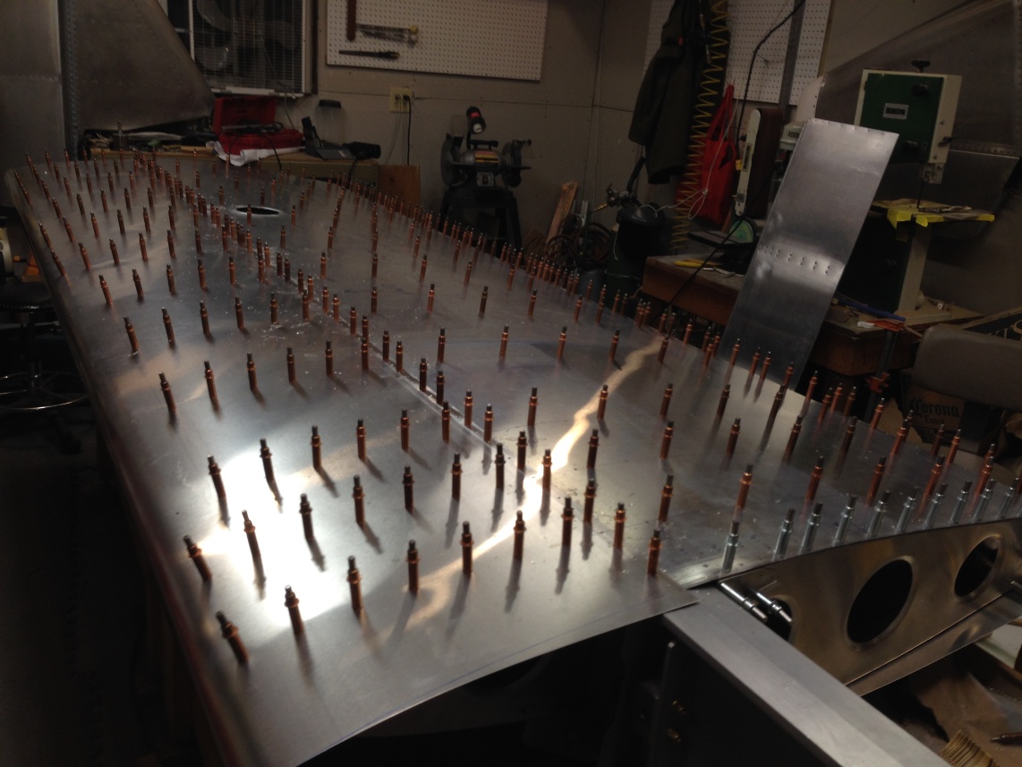
Left Wing Deburring

12/30/2013

Deburring left wing

I spent the remainder of last night with mind numbing deburring of the left wing components. I would like to say I am done but I only spent a couple/three hours at it and part of the time was spent with final trimming of the root doubler. The total time I have spent deburring ( which is mostly sanding the drilled holes with 150, 220 and then Scotch Brite ) is not trivial. I’m not sure if I am over doing the process. Part of the work is in preparation for a thin coat of self etch primer and the alternative is to simply use a deburring tool for holes and edges. I find the deburring tools still require sanding to smooth the edges and the end result is that, as noted, sanding is the preparatory step for priming. I have used a lot of sand paper….


This entry is really just a stalling effort as I wait for the shop area to warm up. The outside temperature dropped to -16 overnight and so while it is certainly warmer in the garage shop it is not near any temperature that would be considered comfortable without a coat and gloves.

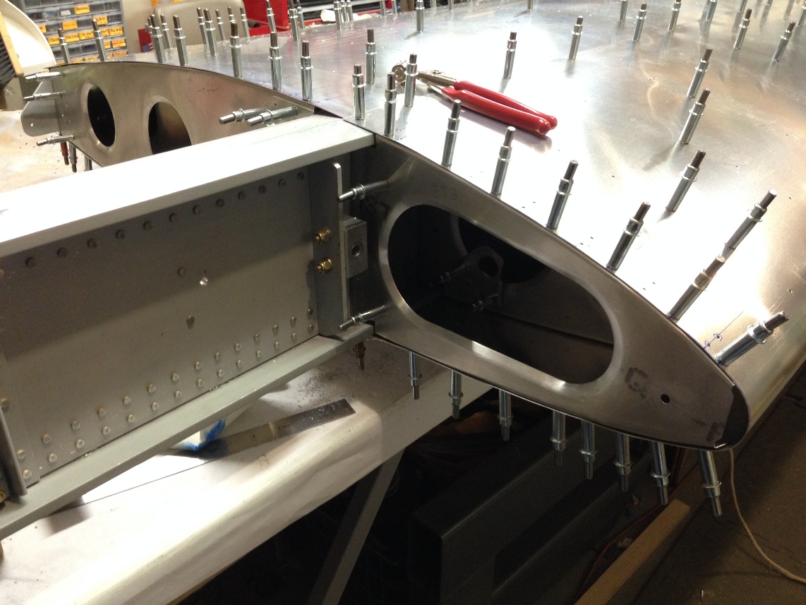
My plans for today are to get as close as possible to priming the skins. As I think about that statement it is really deburring and dimpling. Some of the gussets need to be updrilled and riveted and the bell crank needs to be disassembled oiled and reassembled. Compared to the debur and dimple tasks these little side tracks are hardly worth mentioning.

So, the outside temperature just ticked up to -15F and the shop is probably starting to warm a bit and it’s time to think about the tasks ahead (the air temp is no doubt warm but everything in the room sucks the heat out of you as you touch it or even stand next to it until the heater has time to warm it all up).

My guess at timing:

Deburring ribs 10 min each x 26 gussets = 260 min

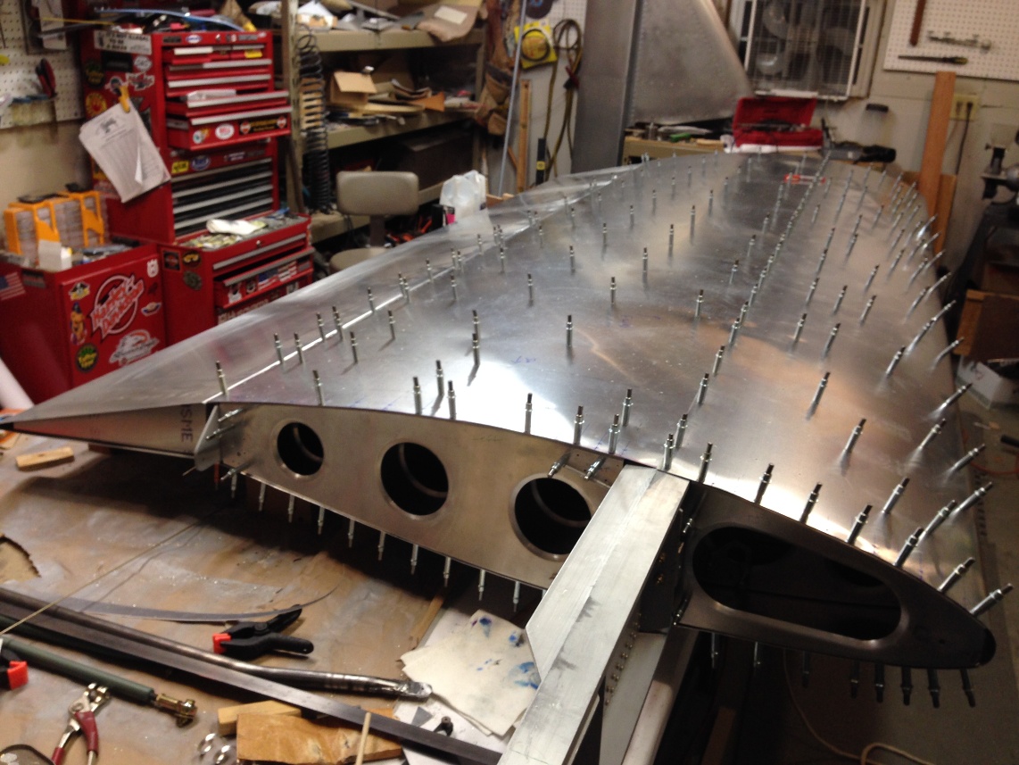
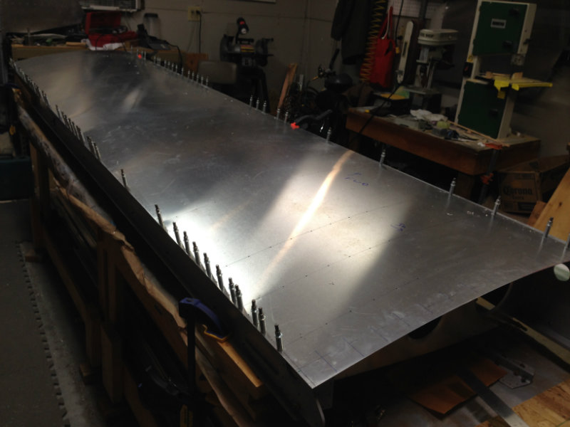
Deburring skins (leading edge is done) 45 min x 2 = 90 min

C.S. and debur main spar 120 min

Dimple all parts 120 min

Priming all parts 90 min

Bell crank assembly 30 min

Final assembly and riveting wing 240 min

Total time~ 16 hours

It is close but I can finish before we leave for our planned New Year’s Eve festivities. I need to try to accelerate the process so I can begin priming by tonight as even with the exhaust fan running the room is uninhabitable without a mask as the primer dries. It is a good idea to prime at the end of the day to let it sit overnight.

Update at the end of the day.

I overlooked a handful of small things with my list above. I have no pictures for today as taking things apart and deburring just does not justify any. I think I’ve put in about 10 solid hours in the plane today, nearly all of it sanding aluminum to debur and I am probably only 1/4 the way to finishing ( that would mean assembling and riveting the wing). So at this rate I will finish before Sunday but that is about all I can hope for.  I will have to settle for that and just be satisfied with two well built wings hanging in my garage while I am away in Singapore beginning next week.

Return To Left Wing Assembly

Left Wing Root Doubler

12/29/2013

Root Doubler and up drilling

I had rough cut the root doubler skin by making a mirror image of the right doubler (we are installing a wing walk on both right and left wings in hopes of finding an elegant method to modify the canopy for entry from both sides).  Much of today was spent match drilling the root doubler and the up drilling the top of the left wing.

When I did the right wing root doubler I sort of puzzled through a method to Match drill the top skin by removing the root rib and drilling the edge of the second (top) skin from inside the wing .  This worked pretty well on the right so I stuck to the plan on the second wing.  The idea being that once enough holes are drill around the perimeter or edge of the skin that, when the wing is disassembled for deburring that the main field of the doubler can be match drilled by laying the skins on top of each other and skip the step drilling and just match drill the skins with a #31 drill bit (#31 because we are using flush rivets. I think I read recently in a note from Sonex that they advocate #32 bits for the leading edge, flush, rivets. The only way this would work is if a silver cleco was used with the #32 bit).

At the end of the day all the match drilling is complete and I finished deburring the leading edge skin and finished prepping and deburring the wing walk (root doubler).

Not much of a write up for today and just a few pics of the steps showing the process to fit the doubler.

IMG_0762_small IMG_0763_small IMG_0764_small IMG_0766_small IMG_0767_small IMG_0768_small

IMG_0769_small

Return To Wings

Left Wing Tip

12/28/2013

The entire day was consumed with fitting and then mounting the left wing tip. I have been getting started no sooner than about 11:00 and the evening often is consumed with the dinner meal and guests (Chele’s sister and husband  often but all three boys are home for Christmas break so a break for dinner is a guarantee). If we have company (which is usually restricted to Fridays and Saturdays) then my day is over  by 5:30.


Nut plates on fiberglass wing tips;

I have the procedure for installing nut plates for flush screws down pretty well. With the fiberglass (f.g.) tip parts there is a need to counter sink (c.s.) the f.g. To accept the dimple of the skin for the flush screws. This dimple, even for the small #6 screws, is pretty a deep c.s., considering the f.g. is only 0.100″ to 0.140″ thick. I was thinking of using solid rivets to anchor the nut plates but after the first few showed consistent cracking of the gel coat, regardless of how I set the squeezer. Pull rivets are more expensive and a little fast due to the time needed for cutting the rivets (all I have are -35  solid rivets and they need to be cut to around. 0.280″ ). I have a few photos to show the cracking and the overall process.

A large portion of the fitting time for the tip is spent trimming, checking and re-trimming the skin to the right length and contour. Once the skinned is trimmed for an acceptable fit, the 1/4″ and 3/8″ setback for the screw holes is marked from the edge. I actually moved the screw centers away from these dimensions (which are what the Sonex plans denote for rivets) by about 1/16″.

Once the screw holes are marked an drilled, the rest of the process is defined and routine. The tip requires 42 nut plates ( not including the face) and so there a lot of holes to drill and c.s.

The first rough cut of the skin is done with my ( invaluable ) electric shear. I bought the shear on sale for $39 at Menards (Tool Shop) and have seen nearly the identical tool with other vendors under other names such as “Klutch” for as much as $89. Quality tools of this design are closer to $200 but after using it to cut ribs and skins on the project I would not want to tackle a “plans built” metal plane without it.

After the rough cutting the rest of the cutting is done with a vixen file. I still need to add a little fiberglass to the tip near the leading edge but I will wait and mess with both wing tips at the same time.

Next, it is time to finish the root doubler and updrill the top skin.

IMG_0758_small IMG_0743_small IMG_0745_small IMG_0746_small IMG_0747_small IMG_0748_small IMG_0749_small IMG_0750_small IMG_0751_small IMG_0752_small IMG_0753_small IMG_0754_small IMG_0755_small IMG_0756_small IMG_0757_small

Return To Left Wing Assembly

Left Wing Landing Light

12/24/2013

After working on and off through the day with a large break for Christmas Eve dinner with the in-laws.  I am about half done with the list I generated yesterday and started the landing light but was confused by the notes from the right wing landing light installation.  The right light appears to be outboard of the design depicted in the Ductworks installation manual.


12/25/2013

Merry Christmas!

I must have been adversely affected by the Christmas Eve dinner last night.  By the time all the guests left last night and I was back in the garage working, it was at least 11:00 before I finished the aileron and got to the light.  My Father-in-law and Brother-in -law lent a hand to close the fwd skin.  This skin was very tight compared to the left wing fwd skin (as I remember).  I think the difference may be partly due to a little more overlap of the trailing edge of the skin over the spar cap, or it could be the fact that when I match drilled the ribs I had the left the fwd skin under the  aft skin (necessary to match drill the trailing edge of the fwd skin).  As mentioned, I managed to finish attaching the aileron after C’eve dinner.  The aileron required that the counter weight bolts be reversed so the nuts did not risk scraping on the 312 rib flair.


Landing light:

The landing light on the right wing appeared to be mounted very close to the outside rib. At least that is what it looked like last night when I was trying to review the installation in the dark garage corner where the wing was hanging.  The Ductworks manual shows the hole biased 1/2″ inboard from being centered between the ribs.  The manual makes a note that the left and right wing have the mounting offset because all the ribs on the plane are oriented the same way (the rib flange is directed inboard on the right wing and directed outboard on the left wing).  This difference between the left and right wing will shift the relative mounting of the reflector by 1/2″ outboard on the right wing. The manual says you “might” want to shift the location of the hole to compensate but then suggests the difference  is not likely to be noticeable.  My thought is that I would move the hole but it’s unclear which wing (right or left) should be moved from the dimensions shown on the plans.  It would be useful to understand what (if any) target distance the light is ideally best to be aimed at.  Understanding this would make it easier to make an adjustment to the hole.

As I understand it, the angle for the right light and the left light are different as on is to be directed for taxi and the other is aligned for the AOA (Angle of attack) during the landing process.  While much of the angle adjustment is vertical, the horizontal angle of the light will change slightly, with the landing approach angle being directed closer to the plane and the taxi light being directed further down the runway (of course, this angle difference may  not be correct for a tail wheel plane as the taxi angle would be roughly the same as a 3 point landing angle and a two point landing or take off roll on a tail wheel would be similar to the taxi angle on a tricycle gear).

I have spent twice as much time thinking about the subject (and writing about it)j as it deserves and I will be installing both wings with the landing lights in the same location.  As it turns out, my initial measurement of the right wing hole (that I installed months ago) was not offset but followed the Ductworks manual so I will do the same with the left wing.

I was able to mark and drill the corner holes for the light and decided to use the nibbler to do most of the cutting for the hole.  I used an abrasive wheel with my Dremel tool on the right wing and it was very unnerving trying to hold the tool steady with visions of having it jump across the leading edge of the wing if it caught the edge of leading edge.  The nibbler may be a bit slower but more relaxing for most of the cutting.  I may end up cutting the actual leading edge with the Dremel but that is about it.

My goal (last year) was to finish the wings by Christmas and a year later I still have not succeeded but I am very close and will likely finish the second wing before the end of the year.  I have to travel to Singapore through most of January for work so not much will get done after the Christmas Holiday so finishing the second wing and having them both hanging by January would be a nice place to finish the year.


12/26/2013

It looks like I might finish the wing if things keep going as they have been.  The landing light installation is completed with the exception of 4 nut plates that need to be install once the skin is off for dimpling. The Ductworks manual suggests that you can install the landing light on a finished wing. I think this is true with the exception of pulling the rivets on the nut plates on the ribs. I’m sure with the right tool it could be done but I tried on the right wing and managed to get the rivet puller stuck and had to remove the rib with the rivet puller stuck to the rivet. On the left wing I will just remove the ribs. Maybe a different puller that did not have such a large open handle requirement when pulling a rivet.

So the second landing light is cut and installed. I would say that all went well except for cutting the plexiglass. I do not look forward to installing the canopy when I have managed to crack both of these little landing light covers while trying to cut them on the band saw.  Yikes !


I started to set up for the wing tip next and the only things left after the tip are up drilling the top side, demurring, dimpling, priming and assembly.  Oh ya, there is the root doubler to finish.  That should not be too bad so I will still predict the wing will be done before New Years!

Return To Wings


Left Wing Forward Skin and Flap

Today, December 23rd, I was able to fit the aft root rib, ( I may have done this yesterday), remount the fwd ribs, drill the fwd skin, match drill the fwd skin and then updrill the entire lower skin area as well as mount the flap.

The wing is ready to flip over and finish the fwd skin and then match drilling and up drilling.

A couple other things to do before breaking it down for deburring, dimpleing and priming the ribs and skins as well as CS the spar caps.

I have to fit the fiberglass tip put the 40 nut plate for the  tip. (3 hours)

Fit the aileron (match drill the hinge and updrill) (15 minutes)

CUT THE LANDING LIGHT!!   (6 hours)This is one of those white knuckle jobs that require plenty of care as soooo much time has been invested in the skin and ribs that I do not want to mess them up.

Speaking of messing up.  The one thing I did today, that I caught before going too far, is not realizing that I did not trim 3/4″ off the leading edge skin and proceeded to match drill the skin to the spar.   Some explanation is needed here; the skin is formed with the top and bottom sections cut to 15-7/8″ so the vacuum forming will bend them symmetrically.  After the leading edge is formed, the lower section (half) of the skin needs to be trimmed by about 3/4″.  I marked the line where the trailing 3/4″ needed to be trimmed after it was formed (last spring) but I did not trim it off at that time.  Although I did mark the drill holes and it was these marks that led me to realize that something was amiss.  Fortunately I did not drill any of the field holesIt all turned out well and I only had to redo the match drilling to the spar after trimming the lower section to proper length.

A close call that would have been a real pain to correct. Lucky me.

Return To Left Wing Assembly

Left Wing Inspection Cover

So close to Christmas and it is clear that the left wing will not be done by the 25th.  Work is the main culprit as Tim tried a couple times to connect  with me but I was fighting against a shipment deadline for equipment on ‘critical” project.  I made my own bed and slept in it but I question if in 10 years that it will seem all that critical. Getting this plane in the air and spending time with my family and friends has to be a bigger priority. Something to work on.

Well, today and yesterday were pretty good as far as the getting things done on the plane.  I almost made a mistake today that would have set me back more than a few days.  I’ll get to that  but first the progress.

Yesterday, despite numerous interruptions with honey do list things, I was able to start and finish the inspection cover and the cut out for the tie down in the lower skin. I really like the squeezer that Gary Hall loaned us.  It is really the ticket for installing nut plates.  Tim and I decided to  use nut plates to mount the inspection covers.  While I am behind the decision it turns a 3 minute drill and screw into 3 hours when you want to have the screws countersunk (self tapping screws are what are called out on the plans).  I have a few pictures  but to make sense of what is going on I should explain that buying countersunk nut plates would be faster (and probably smarter) but what we had were a large collection of flat nut plates.  I don’t know the MS number for the nut plates we have but I thought it would be easy enough to just add a small piece of aluminum behind the skin to provide the depth to counter sink for flush mounting rivets and mounting screws.

The procedure is pretty straight forward but it is important to keep track of what holes should be drill first and at what diameter in order to best keep everything aligned.  The procedure I followed was this:

1) drill major inspection hole and make a cover

2) Mark the center line and cross  line for screw holes in cover and skin

3) Drill screw holes with #40 bit in cover

4) Align and match drill screw holes to align cover to skin

5) Cleco nut plate to skin and drill mounting holes with #40 bit.

6) Cleco cover to skin and updrill to #30.

7) dimple cover and skin for screw (this will likely be a #6 dimple die

8) updrill (match drill) previously dimpled holes to #21 (for ample clearance for screws)

9) dimple mounting holes on skin

10) cut small blocks of 0.060″ to mount nut plates.

11) match drill aluminum blocks to nut plates.

12) counter sink aluminum blocks for counter sink depths on skin for mounting rivets and screws.

13) debur and prime mounting blocks and skin.

14) rivet aluminum and nut plates to skin (this is where the squeezer works so well.  Just by measuring the stack up of parts the rivets can be cut to length and the rivet squeezer can be set to the proper compression and it works like a champ)


Only 14 simple steps and you’re done.

Return To Left Wing Assembly

Left Wing Bottom Skin Level And Match Drill

Today was perhaps a good example of how quickly things can move along in the assembly process if all the parts are made (like a kit, instead of scratch building as we are) and if we don’t mess around thinking too hard about stuff.

Tim was busy until around 1:30 and I had a load of issues to attend to with regard to work (I so much for vacation but at least I could take care of it without leaving home).   The morning was spent catching up on email and getting things prepped for dinner (gotta keep the “sweetie” happy).  After all that it was almost 12:30 before I got into the garage to even turn on the heat.  I was in the garage actually doing something by time Tim arrive.  I had been on a conference call and simple kept my headset on while on mute and listening in as i drilled holes in the skin to finish the top side match drilling.

When Tim arrived i had the match drilling pretty much done and while I pulled out the bottom skin Tim cleaned up the rear spar trailing edge to file off any alignment error between the skin and the spar.

We flipped the wing over and Tim aligned the bell crank brackets to the upper skin while I worked to level the then skin by supporting each of the four corners with blocks and shims to insure the wing was flat (not having any wash out or pitch variation from root to tip.  

Left Wing Level Bottom Side Up

The process of squaring and leveling the wing (as mentioned earlier) can be done a couple different ways but the bottom line is that (in my view) you need to have an image in your mind of the process you are involved in.  I spent a good part of my youth working for my “old man” building houses and even did it for a few years before and during my college years.  The process of squaring a wall so that when you stand it up it will be plump is very similar to assembling a wing to be square and not have any wash out. For me it is almost an intuitive process that I know most framing carpenters would find easy.

The process can be broken down into two primary steps.  The first skin must set the wing with regard to square (which is not terribly hard but a bit of a challenge to find a reference).  The second step, once the wing is held square by the first skin, is to insure it is flat (no wash out).

To square the wing it is also a good idea to have it close to level, although not necessary to be exact, it will be needed on the second side skinning so the procedure is good practice.  Once level it is easiest to find four points that define a parallelogram. The first two points on the skin are the wing station 22-3/4″ center line at the center of the main spar and the trailing edge of rear spare at the same 22-3/4″.  These two points will be  marked on the upper and lower skin as the intersection of the center line (where the holes are drilled) and the edge of the skin.  If you cut our skin carefully (as you should) the final width should match the plans and the skin should be square (don’t trust factory cut sheets of aluminum to be square).  Even though the root and the wing tip have very irregular contours, the center line of the first rib in from each end (rib #1 and rib #12) should form a perfect rectangle on the wing skin.  The second two points are the same position on theT #12 rib. The key characteristics of a rectangle is that each of the opposite sides is the same length and the angles where the adjacent sides intersect should form 90 degree angles. The wing skin when laying flat provides a perfect pattern to align the wing box.  The only task that remains is to identify the reference point that make a rectangle on the skin, and mark them on the wing box.

To really describe the above process i need to generate a picture or some sort of graphical layout.  maybe that will be a task for later.

Once the wing is held square by the skin on one side of the wing, attaching the second side will give the wing 3 dimensional rigidity.  Holding the wing flat, or vertical and planar, when skinning the second side will insure that there is no wash out in the final wing structure.

If all of the wording above is confusing, I hope it is because of my poor explanation and not the readers inability to understand the concept of square and flat.  Otherwise, you are doomed.

Wing Skin Drill Jig For Between Ribs

The bottom line for the  night.  The bottom skin is fully match drilled and the inspection hole is cut.  Tomorrow I need to determine if I want to add the fwd ribs and skin or updrill the aft ribs.  it probably does not matter but immediately after the leading edge is skinned I will proceed to cutting in the landing light for the left wing. That could happen tomorrow…

 Return To Left Wing Assembly

Left Wing Skinning Top

Left wing skinning

December 15, 2013

The left wing is expected to go much faster than the right as all the parts have been pretty much completed and the right wing assembly included welding the control rods.  In a sense, the left wing assembly should go at least as easy as building from a kit, maybe even easier since the right wing had just been completed so the assembly procedures were well understood.

The left wing box had also been assembled and updrilled to #30 (1/8″) as well but none of the gussets had been riveted and the majority of the ribs were not deburred.  Although the ribs needed to be deburred again after being match drilled to the skins, I was thinking of riveting the gussets to the ribs before assembling the wing.  Plans changed and I ended up working the last two days of the week, contrary to my original plans.  This led to not having all the ribs ready to prime and rivet the gussets so I chose to begin assembling the wing box on Saturday morning.

Tim and I got together on Sunday afternoon and while he finished deburring the missing aft ribs I finished deburring the fwd ribs.  After the aft ribs were deburred and clecoed in place the wing box was leveled, squared and clamped to the bench top.  

Tim and I discussed how many builders skin the wing vertically while I was proceeding as I did on the right wing by leveling and squaring it while flat on the table.  I am confident either would work and any discussion on which might be better might be a waste of time.  I feel it is easier to constrain the wing when it is flat on the table, which is my primary reason for why I would rather have it horizontal on the table.

Anyway, once Tim was comfortable with what I was doing (or tired of going over the procedure verbally) we moved forward and found a location that was as level and square.   We then laid the pre-marked top skin on the box and checked the alignment of the marked hole center lines that were yet to be drilled, with the centers of the ribs.

We then checked the only reference dimension on the prints that provided an alignment for square.  This was the wing station zero point (also the center of the wing span) to the rear spar attached hole.  This measurement was supposed to be 19.0″  The original measurement we checked did not come up to 19 inches  but after a little review it was apparent that there was a bend in both thee main and rear spar that was distorting the measurement.

Tim had to leave and so I had time to drill the top skin and mount it on the wing box.  Mounting the skin provides an easy method to straighten the spar out by match drilling the rear spar, beginning from one end and making sure the trailing edge of the spar was flush with the wing skin.  After this is done the wing can be squared by checking that the centers of the drill holes aligns with the rib centers at the ends (the middle of the ribs are unreliable as they tend to wander a bit until match drilled to the skins).  It is the rib centers marked on the spars that make the best reference for the skin hole centers.

With the aft spar match drilled to the skin the wing box can be clamped at the main spar and the 19″ reference dimension can be checked.  This time the measurement came out to as close to precisely 19.0″ as I can measure.

Left Wing Station Zero
Left Wing Station Zero Ruler Value
Rear Spar Bolt Hole For Measuring Wing Square-ness

I have pictures of the 19″ reference measurement as well as the alignment of the skin center lines with the rib center lines.

A few pictures of the semi finished match drilled skin and wing box and that is about as far as i am going to get tonight.  Tomorrow Tim and I expect to both be able to work on the plane during the day as we both have “vacation to take up” as my friends if Singapore say before it evaporates at the end of the calendar year.

Return To Left Wing Assembly

Right Wing Sling

Right Wing Sling

December 14, 2013

The right wing was done almost a week ago and I have done little on  the plane since then.  Mostly  because work  has really  been taxing at the end of the year and I need to take my remaining vacation or lose it by December 31st.

I am off until the end of the year (at which point I will likely be traveling for the first three weeks of the year for work so whatever I don’t get done through the rest of December will sit until February.

A few small things did get done during the week.  I cleaned out the lower section of my work bench (all 12 feet of it) and moved the aluminum angles off the 12′ rolling material rack. This left room on the rack to hang the complete right wing.  I struggled for a few days after the wing was completed trying to come up with an elegant method to store the wing.  I wanted it secure and safe but still be relatively easy to get at for reference while completing the left wing.  I came up with using a canvas tarp and with a few simple ropes making a sling that I could either hang on the wall or as I alluded to above, hang on the back of my material cart.

Slipping the wing into the sling was a two man job and Tim was able to stop over Wednesday night after work to lend a hand.  I have a few shots of the tarp with and without the wing on and I think it worked out pretty  well.  I have a better idea for the next wing, which is to buy another tarp and secure the tarp around the wing while the wing is on the bench and provide a rope handle to simple pick up the wing near the center of gravity.  I could then just carry it over to where I want to  hang it and hook the handle on whatever I have decided will work best (a set of hooks on the wall or off the material rack).

So, my goal for the next two weeks is to see if I can assemble the left wing and get it hanging on the wall before I have to return to work.  Tim had a couple days off last week where I was stuck finishing things up for the year end and i know he was dying to come over (while his kids were still in school and he had time off).  Hopefully this coming week will work out better and we can make some real progress with two of us in the shop.

Left Leading Edge
Left Wing Walk

We might add a wing walk to both sides if we modify how the canopy opens.

Return To Right Wing Assembly

Right Wing Finish

Dan
Dec. 8, 2013    Last day for major work on right wing
There were plenty of interruptions yesterday and today but the right wing is finally closed in and riveted with not much but a few small items to do before wing installation on the fuselage.

Right Wing – Tip Side
Tie Down Ring & Inspection Plate
Right Wing Tip Installed (Wing Upside down)
Right Wing Tip Installed (Wing Upside down, Note Landing Light Pocket)
Right Wing – Note Pitot, Static, & AOA tubes
Right Wing – Inside view of wing tip through the landing light cut out (wing is upside down)

Left To Do:
Paint control rods
Add nut plates for surface screws on wing tip
Trim pitot, static and AOA tubes and connect to lines.
Attach and trim wing doubler skin after wing is fitted to fuselage

A few things to note.

The rivets in the bags need to be watched carefully because they are not perfectly sorted. Either we inadvertently dropped a few CCP rivets in the CCC bag or they came that way. in either case, I caught them before pulling the rivets but it is a lesson to not be too casual or in too much of a hurry when putting in large numbers of rivets like those in the wing assembly.

Using the flat piece of 3/16″ aluminum between the rivet gun and the rivets was a big improvement over just using the rivet gun tip. This was particularly true when riveting the leading edge skin to push with heavy and even pressure to keep the skin tight to the ribs. It probably helped a lot to have the skin well formed with the vacuum method but even so, I think it helps to be able to press hard on when riveting the leading edge.

I was planning on hanging the wings up on the wall in the garage but I think I can rearrange the material in the rolling rack and put the wings on the rack.

Modifying the rack with have to be the next thing to do so I can clear off the bench to assemble the left wing.

Return To Right Wing Assembly