Elevator trim

The standard Sonex elevator trim is what we are implementing, despite all the little tweaks from the standard design, at some point you have to just stop modifying and just build the plane.

OK, a few changes but really just minor. The “swivel” at the control arm end is called out as a standard part from Asuza. It’s fine but we had modified the Bowden cable mounts on the engine and the experience with that design provided an easy modification to an AN bolt that has a more positive clamp on the cable.

We’ll have to add some detail on the design, should it be worthy of being copied.

Below are a couple photos of the design and implementation.

This is the trim tab from the bottom with added reinforcement and showing the swivel constructed from an AN3 bolt. Why not just use the “Z” bend on the bowden center cable? Mike Smith changed his out and the assumption is that the bend could be problematic. Not sure if the change is justified.

The control handle is basically the same as what is shown on the Sonex plans. It works well as is. The only change is the swivel.

Control handle with only minor changes from plans. The swivel is a modified AN3 bolt

Control Rod UHMW Guide Blocks

The UHMW guide blocks for the elevator control rod will squeak at the two extremes of the motion. The hole in the blocks are a straight bore. The control rod moves up and down slightly with the mounting pivot arm. Dan’s solution is to bevelthe bore slightly to allow the change in height of the control rod. The rod is still supported and no squeaking due to interference.

Turtle Deck Ribs

3_16_2014
Fuselage status
After completing cutting and drilling the larger sheet parts for the fuselage over the last few weeks I started working on the turtle deck rib formers.  We had purchased the rib forming block kit long ago and the fuselage ribs were the only ones that had not been converted to parts (although to be fair, the only other ribs other than one fire wall rib former were for the wings).
So I finished making copies of the rib formers for the fuselage (yes, and the one for the fire wall).  The #1 fuse rib is part number F20-01 (R and L).  I had set aside a piece of 032 for these two pieces and through the course of the day was able to finish one of the two.  When I laid it up along the turtle deck skin and bent the skin around the rib it seemed to follow the edge of the cut skin quite well.  These complex edge cuts of the skins make me a little nervous as they are laid out as a table in the drawings and you need to “connect the dots” and generate a smooth curve to cut them.  I must be getting better at it because the wing tips did not appear to really follow the layout (despite the fact that we generated a CAD plot of the complex shape).  For the wings I cut the skin long and trimmed to fit the tip (a method I would recommend) but for the turtle deck (which is quite a bit more straight forward) I simply marked it on the aluminum and cut to the smooth curve I generated from the points.
Another 4 hours and I should have all the turtle deck parts (ribs) formed.  Then it will be on to bending some of the other parts with the brake for all the cross members within the fuselage and then I am expecting to start building the numerous angle pieces as they are needed.
One of the distractions today was a trip over to a friend of Tim and mine from work.  Eric Hokenson.  Eric is a rod builder (and quite a good one at that).  Eric has a shop that is the envy of many a handy man.  There are few tools he does not have, English wheels, band saws, brakes, shears, end mills….where do I stop?  Not only does Eric have a lot of tools but he knows how to use most far better than 95% of the craftsman owning the same tools.  Anyway, Eric has a collection of tubing benders and one of the issues Tim and I have been struggling with is the canopy.  We have imagined building a gull wing canopy but recently I started getting cold feet as the details started to worry me.
One of the suggestions Tim made that I (at first) discarded was beefing up the front wind screen bow by substituting 4130 for the existing aluminum ½” tubing.  The advantage is that 4130 is significantly stronger and it can be welded, so a center overhead section could be easily attached to it.  Well, Eric has a couple nice tubing benders and I am thinking that maybe using 4130 and Eric’s tubing bender could maybe get me back on track with the center overhead section necessary for a gull wing canopy.  We’ll see if I can talk myself back into this again ‘cause I sure don’t like the current design of the side opening canopy the Sonex has.

Return To Fuselage

Turtle Deck Cut Out + Seat Sling

February 23, 2014
Turtle Deck Cut Out & Seat Sling

The turtle deck sections were marked and cut without incident last week. The only issue I had at all was that the power went out do to a massively wet and heavy snow storm on Thursday night.  The total snowfall was only 12 or 14 inches but it started as a rain and snow mix and by the time  the air cooled and the snow really began to accumulate the trees and power lines were loaded with ice and snow.

Turtle Deck Marked Out

The plans do not mention it but I am planning on match drilling the seam at the top of the turtle deck with the two sections laid flat to insure the holes line up. It seems obvious as I write this but the plans show two halves being drilled as separate pieces and only later laid flat to be riveted with the seam channel. The two sections I am referring to are F20-06 (R and L) and the seam channel is F20-07.

After the turtle deck sections the next largest uncut fuse piece was the cockpit floor, F16-01. This was to be cut from 0.032″ but there were two more pieces needed at 0.025″, the aft bottom skin (that needed to wait until we picked up one more sheet) and then the seat sling. We were planning on installing the sport trainer controls (center brake, flaps, throttle, etc.) and the lowered seat option. Together these two options required we follow C06 through C09.

There a bunch of changes and substitutions related to these four sheets and it is best to carefully read and then review the implications of the sheets. Tim and I are slowly getting up to speed with these sheets and I’m sure by the time we’re done it will seem very straight forward but for now it is often confusing.

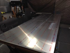
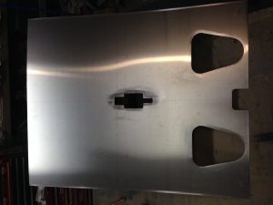
I finished the modified seat sling cut out tonight. I then moved the last full 4’x12′ sheet of 0.032″ sheet aluminum to the table to be cut into the lower side panels, F13-01, lower cockpit skin, F16-01, glare shield and control panel. We need to be sure we have a large enough piece for the control panel to add a few inches to the bottom as others builders have done for a little more instrument room.

Return To Fuselage

Rear Fuselage Side Panels

2/8/2014

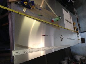
Starting the layout of fuselage parts. The plans has the side panels as the highest numbered sheets. Tim and are expecting that we will be at least one sheet of 0.025″ aluminum short. This is due to (likely) some careless cutting on my part, way back when we were fabricating the control surfaces. At that point it appeared as though we had at least one sheet of 0.025″ surplus and when I was cutting out the control surfaces I simply continued cutting them in sequence from a single sheet. The general rule of thumb for consuming sheet goods for best material use is to cut (or lay out) the largest pieces first and to nest the next smaller sized pieces within those larger cut outs. By ignoring this rule and in addition, having to recut one aileron due to a mishap during trimming (grrrrr) I likely set the stage for needing to make another trip to the local aluminum vendor. Lucky for us there is a local vendor for 6061 or I would be paying for shipping.

So Tim and I laid out the large pieces for the fuselage and it is clear we are at least one short. I would say that the fuse parts require the same level of attention to the plans as all the rest. I read through the F26-01 skin multiple times before I realized I missed the detail at the skins are mirror images except for the inspection hole AND the hole for the rudder control slot. I have the two skins stacked to lay them out for drilling and fortunately caught this difference before I drilled any holes.

I think the best procedure is to cut out and complete fabrication and drilling of all the major fuselage skins before heading out to pick up the needed additional sheet as there is little room for error on the large parts before we would need to add to our order. Hopefully that will not be necessary.

Return To Fuselage


Left Wing Priming 1

2014_1_1

I finished all the deburring this afternoon just as Tim made it over. We spent the afternoon dimpling and by the time Tim left at about 5:00 all that was remaining was the inner areas of the skins and the fwd ribs ( I had used the squeezer to dimple the perimeters) and the leading edge. Just as I thought I was done with the fwd ribs and skins, the hinges caught my eye but in any case, be 8:30 all of the dimpling was done.

I cleaned up and decided to put a coat of primer on the inner surface of the skins only and leave the ribs for tomorrow. It’s 10:30 as I write this and the skin priming is done. I will let the fan run for a little while and then go out and turn down the heat and the fan off for the night. It’s easy to just let the exhaust fan run in the summer but in the winter, especially when it is as cold as it has been ( well below zero every night and just barely above zero if at all in the day) it will get equally cold in the shop if I run the exhaust fan without heat and it seems so wasteful to run the heat at night. So the plan is no exhaust and low heat to help the primer dry.

If I can prime the ribs tomorrow night I will be able to work on riveting the wing on Friday night and maybe finish assembly on Saturday if there are no interruptions. Realistically I am thinking there is a rather slim chance of having either Friday night or Saturday open to work on the plane as it is getting perilously close to my departure Singapore. I expect that I will have loads to do without spending any time on the plane. It will just have to wait until I return.

IMG_0774 IMG_0777 IMG_0778

Return To Left Wing Assembly

Left Wing Deburring

12/30/2013

Deburring left wing

I spent the remainder of last night with mind numbing deburring of the left wing components. I would like to say I am done but I only spent a couple/three hours at it and part of the time was spent with final trimming of the root doubler. The total time I have spent deburring ( which is mostly sanding the drilled holes with 150, 220 and then Scotch Brite ) is not trivial. I’m not sure if I am over doing the process. Part of the work is in preparation for a thin coat of self etch primer and the alternative is to simply use a deburring tool for holes and edges. I find the deburring tools still require sanding to smooth the edges and the end result is that, as noted, sanding is the preparatory step for priming. I have used a lot of sand paper….


This entry is really just a stalling effort as I wait for the shop area to warm up. The outside temperature dropped to -16 overnight and so while it is certainly warmer in the garage shop it is not near any temperature that would be considered comfortable without a coat and gloves.

My plans for today are to get as close as possible to priming the skins. As I think about that statement it is really deburring and dimpling. Some of the gussets need to be updrilled and riveted and the bell crank needs to be disassembled oiled and reassembled. Compared to the debur and dimple tasks these little side tracks are hardly worth mentioning.

So, the outside temperature just ticked up to -15F and the shop is probably starting to warm a bit and it’s time to think about the tasks ahead (the air temp is no doubt warm but everything in the room sucks the heat out of you as you touch it or even stand next to it until the heater has time to warm it all up).

My guess at timing:

Deburring ribs 10 min each x 26 gussets = 260 min

Deburring skins (leading edge is done) 45 min x 2 = 90 min

C.S. and debur main spar 120 min

Dimple all parts 120 min

Priming all parts 90 min

Bell crank assembly 30 min

Final assembly and riveting wing 240 min

Total time~ 16 hours

It is close but I can finish before we leave for our planned New Year’s Eve festivities. I need to try to accelerate the process so I can begin priming by tonight as even with the exhaust fan running the room is uninhabitable without a mask as the primer dries. It is a good idea to prime at the end of the day to let it sit overnight.

Update at the end of the day.

I overlooked a handful of small things with my list above. I have no pictures for today as taking things apart and deburring just does not justify any. I think I’ve put in about 10 solid hours in the plane today, nearly all of it sanding aluminum to debur and I am probably only 1/4 the way to finishing ( that would mean assembling and riveting the wing). So at this rate I will finish before Sunday but that is about all I can hope for.  I will have to settle for that and just be satisfied with two well built wings hanging in my garage while I am away in Singapore beginning next week.

Return To Left Wing Assembly

Left Wing Root Doubler

12/29/2013

Root Doubler and up drilling

I had rough cut the root doubler skin by making a mirror image of the right doubler (we are installing a wing walk on both right and left wings in hopes of finding an elegant method to modify the canopy for entry from both sides).  Much of today was spent match drilling the root doubler and the up drilling the top of the left wing.

When I did the right wing root doubler I sort of puzzled through a method to Match drill the top skin by removing the root rib and drilling the edge of the second (top) skin from inside the wing .  This worked pretty well on the right so I stuck to the plan on the second wing.  The idea being that once enough holes are drill around the perimeter or edge of the skin that, when the wing is disassembled for deburring that the main field of the doubler can be match drilled by laying the skins on top of each other and skip the step drilling and just match drill the skins with a #31 drill bit (#31 because we are using flush rivets. I think I read recently in a note from Sonex that they advocate #32 bits for the leading edge, flush, rivets. The only way this would work is if a silver cleco was used with the #32 bit).

At the end of the day all the match drilling is complete and I finished deburring the leading edge skin and finished prepping and deburring the wing walk (root doubler).

Not much of a write up for today and just a few pics of the steps showing the process to fit the doubler.

IMG_0762_small IMG_0763_small IMG_0764_small IMG_0766_small IMG_0767_small IMG_0768_small

IMG_0769_small

Return To Wings

Left Wing Tip

12/28/2013

The entire day was consumed with fitting and then mounting the left wing tip. I have been getting started no sooner than about 11:00 and the evening often is consumed with the dinner meal and guests (Chele’s sister and husband  often but all three boys are home for Christmas break so a break for dinner is a guarantee). If we have company (which is usually restricted to Fridays and Saturdays) then my day is over  by 5:30.


Nut plates on fiberglass wing tips;

I have the procedure for installing nut plates for flush screws down pretty well. With the fiberglass (f.g.) tip parts there is a need to counter sink (c.s.) the f.g. To accept the dimple of the skin for the flush screws. This dimple, even for the small #6 screws, is pretty a deep c.s., considering the f.g. is only 0.100″ to 0.140″ thick. I was thinking of using solid rivets to anchor the nut plates but after the first few showed consistent cracking of the gel coat, regardless of how I set the squeezer. Pull rivets are more expensive and a little fast due to the time needed for cutting the rivets (all I have are -35  solid rivets and they need to be cut to around. 0.280″ ). I have a few photos to show the cracking and the overall process.

A large portion of the fitting time for the tip is spent trimming, checking and re-trimming the skin to the right length and contour. Once the skinned is trimmed for an acceptable fit, the 1/4″ and 3/8″ setback for the screw holes is marked from the edge. I actually moved the screw centers away from these dimensions (which are what the Sonex plans denote for rivets) by about 1/16″.

Once the screw holes are marked an drilled, the rest of the process is defined and routine. The tip requires 42 nut plates ( not including the face) and so there a lot of holes to drill and c.s.

The first rough cut of the skin is done with my ( invaluable ) electric shear. I bought the shear on sale for $39 at Menards (Tool Shop) and have seen nearly the identical tool with other vendors under other names such as “Klutch” for as much as $89. Quality tools of this design are closer to $200 but after using it to cut ribs and skins on the project I would not want to tackle a “plans built” metal plane without it.

After the rough cutting the rest of the cutting is done with a vixen file. I still need to add a little fiberglass to the tip near the leading edge but I will wait and mess with both wing tips at the same time.

Next, it is time to finish the root doubler and updrill the top skin.

IMG_0758_small IMG_0743_small IMG_0745_small IMG_0746_small IMG_0747_small IMG_0748_small IMG_0749_small IMG_0750_small IMG_0751_small IMG_0752_small IMG_0753_small IMG_0754_small IMG_0755_small IMG_0756_small IMG_0757_small

Return To Left Wing Assembly